Electronic equipment case structure

a technology for electronic equipment and case structure, applied in the direction of electrical apparatus casing/cabinet/drawer, instrument, solid-state device details, etc., can solve the problems of affecting the operation of the electrical apparatus, and the failure of the latch structure to couple the unit body in an upright manner. , to achieve the effect of increasing the surface area

Inactive Publication Date: 2007-01-23
INVENTEC CORP
View PDF9 Cites 8 Cited by
  • Summary
  • Abstract
  • Description
  • Claims
  • Application Information

AI Technical Summary

Benefits of technology

[0005]In view of the aforesaid problems, the primary object of the present invention is to provide an electronic equipment case structure to hold an electronic equipment and to provide bracing and cooling effect when housed in a computer case. To achieve the foregoing object, the case structure according to the invention includes a shell and a blade-cooling portion mounted onto the outer surface of the shell. The blade-cooling portion has a plurality of protrusive sections that are spaced from one another at a selected distance. The blade-cooling portion may be formed in varying styles. Besides having the protrusive sections on the surface, the blade cooling portion may also have a plurality of bosses to cover the entire surface that have a cross section of a square or an arched shape to increase the surface area. The bottom side and topside of the blade-cooling portion are not covered by the bosses and are flat and smooth surfaces to provide a tight coupling with the elements. A cooling recess may be formed between two neighboring protrusive sections. The cooling recess also has a plurality of sub-protrusive sections, which also have a cross section of a square or an arched shape to increase the surface area.
[0006]The electronic equipment is housed in the electronic equipment case. When the electronic equipment is in use, it generates heat. The case is made of material of a higher thermal conductive coefficient such as aluminum, copper, silver or steel to transfer the heat to the blade-cooling portion. The blade-cooling portion has a greater amount of radiation area to increase the cooling efficiency. In addition, the case and the contact elements are spaced from each other at a selected distance and can provide a bracing effect. The protrusive sections provide the bracing effect. The bottom side of the blade-cooling portion is in contact with the surface of the shell. The cooling recess that has the sub-protrusive sections and sub-recesses is not connected to any element. To improve the cooling effect, the shell and the blade-cooling portion are made of material of a higher thermal conductive coefficient. In addition, the blade-cooling portion also has bosses or sub-protrusive sections formed on the surface to increase the surface area. Therefore the total radiation area increases and the cooling efficiency is enhanced.

Problems solved by technology

In the design of a computer system, cooling is an important issue.
If the heat is not dispelled, the element will malfunction or even be damaged.
However, the latch structure can only couple the unit body in an upright manner, not in a paired and juxtaposed manner.
While it provides cooling and a limited support, the unit bodies are not coupled securely, and are prone to loosen and tumble.
This could cause trouble.
Moreover, the latch structure cannot increase the cooling area very much, and the improvement of the cooling efficiency is limited.

Method used


Image

  • Electronic equipment case structure
  • Electronic equipment case structure
  • Electronic equipment case structure

Examples


Embodiment Construction

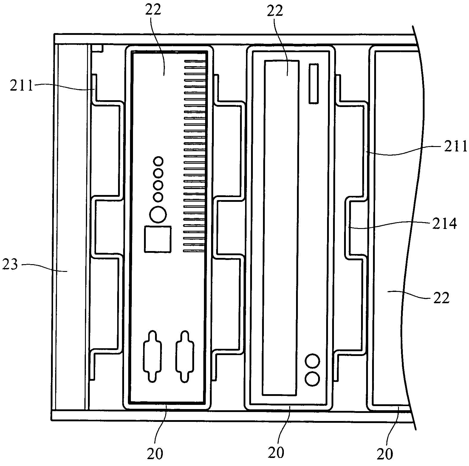
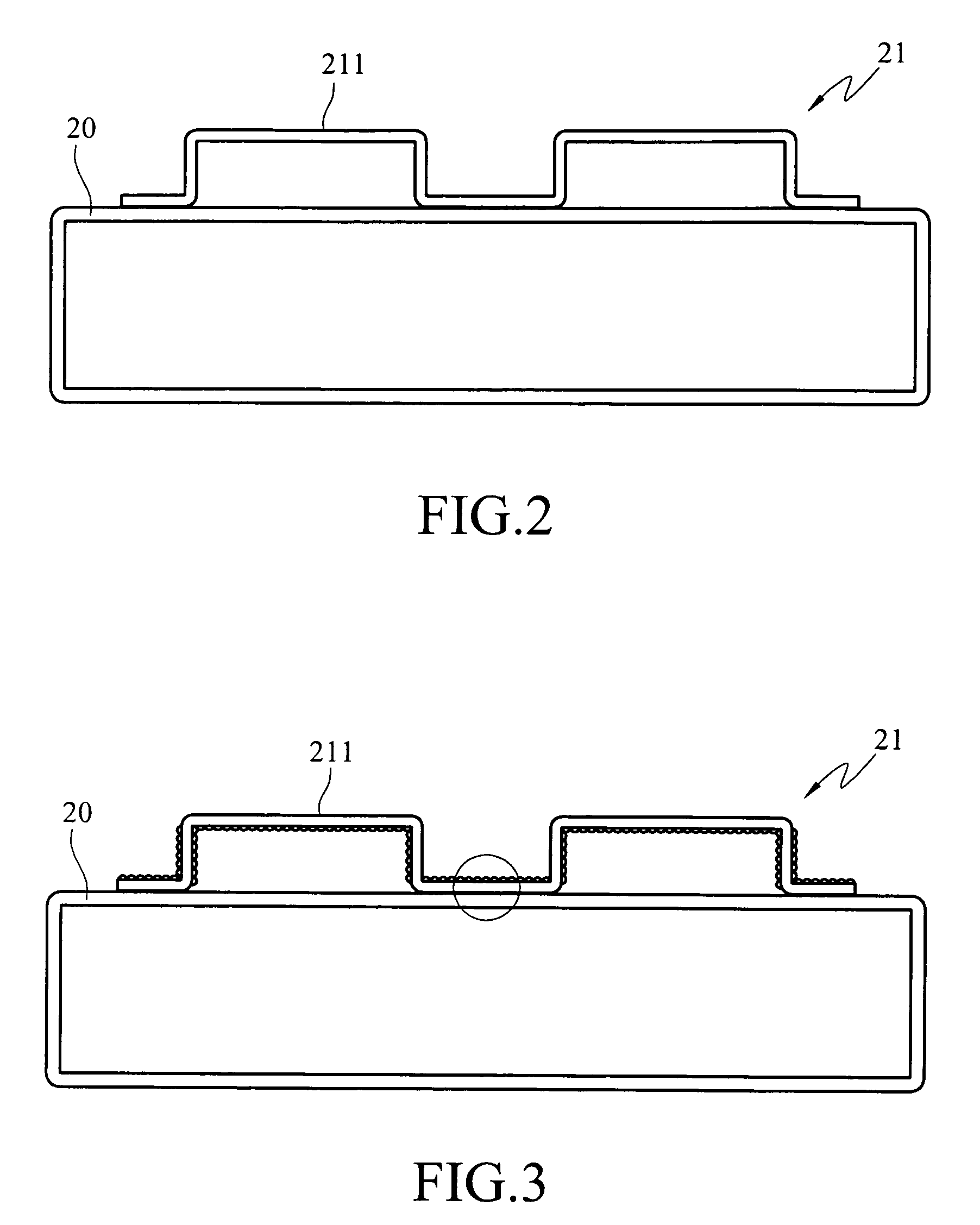
[0014]Referring to FIG. 2, the electronic equipment case structure according to the invention includes a shell 20 and a blade-cooling portion 21. The shell 20 is hollow and has a housing compartment to hold electronic equipment. The blade cooling portion 21 includes a plurality of protrusive sections 211 that are spaced from one another at a selected distance to form a zigzag profile, to brace other elements that are in contact with the case, to provide support and partition. As the electronic equipment housed in the case is a heat-generating element, the case also should have a cooling function. Hence the shell and the blade-cooling portion are made of material of a high thermal conductive coefficient, such as aluminum, copper, silver, steel or the like. Besides using the material of a high thermal conductive coefficient, the cooling efficiency may also be enhanced by increasing the surface area of the blade-cooling portion 21. This may be accomplished by distributing a plurality o...


PUM


Abstract

An electronic equipment case structure aims to provide bracing and cooling for an electronic element. The electronic equipment is housed in the case which has a plurality of protrusive sections on the outer side that are spaced from one another at a selected distance to serve as a bracing structure. By means of using material of a high thermal conductive coefficient and increasing the radiation area, cooling efficiency increases. The electronic equipment case structure can provide a bracing and cooling function.

Description

FIELD OF THE INVENTION[0001]The present invention relates to a case structure and particularly to a case for holding electronic equipment to provide support and cooling.BACKGROUND OF THE INVENTION[0002]In the design of a computer system, cooling is an important issue. Every electronic element will generate heat during operation. If the heat is not dispelled, the element will malfunction or even be damaged. Hence cooling is necessary. The most common approach to dispel heat is to couple the heating element with a thermal conductive element. The thermal conductive element aims to enlarge the cooling area of the heating element so that cooling efficiency may increase. For instance, U.S. Pat. No. 6,532,141 discloses an electronic element cooling structure, referring to FIG. 1 of that patent application. It has a body containing a plurality of coupling sections. Each coupling section has screw threads. The body further has a thermal conductive duct running through the center of the coupl...

Claims


Application Information

Patent Timeline
Patent Type & Authority Patents(United States)
IPC IPC(8): H05K7/20
CPCG06F1/181H05K7/20545H05K7/20418G06F1/20
Inventor YA, YUN-JIE
Owner INVENTEC CORP
Why Eureka
Try Eureka