High-directivity columnar convex surface conformal reflector antenna based on meta-surfaces
A metasurface and reflective surface technology, applied in antennas, electrical components, etc., can solve problems such as beam calibration of convex mirrors that cannot be solved, and achieve the effect of versatility
- Summary
- Abstract
- Description
- Claims
- Application Information
AI Technical Summary
Problems solved by technology
Method used
Image
Examples
Embodiment 1
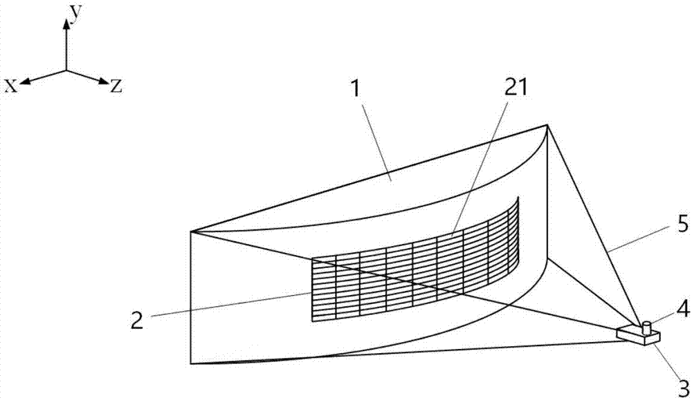
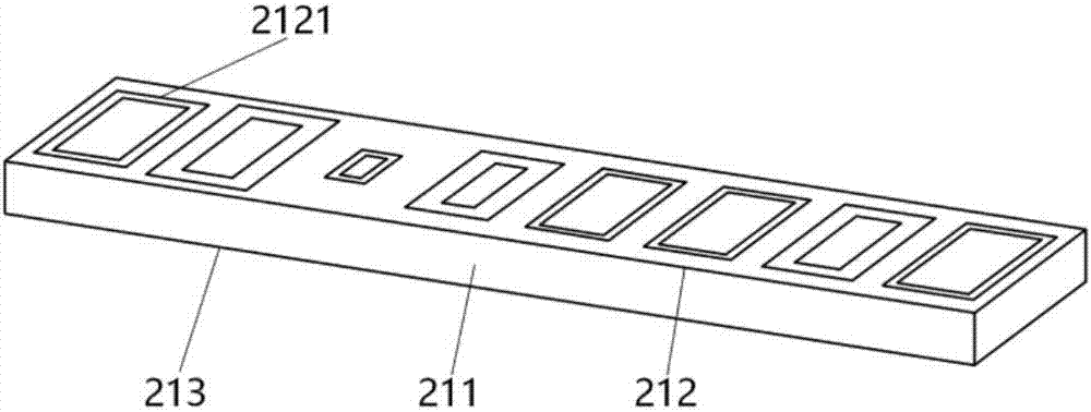
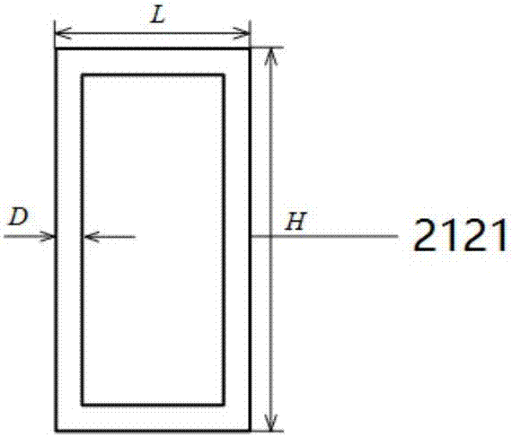
[0026] refer to figure 1 , a highly directional cylindrical convex conformal reflector antenna based on a metasurface, including a cylindrical convex carrier 1, a convex mirror 2, a feed source 3, a coaxial conversion joint 4 and a support structure 5, and the convex mirror 2 consists of 12× It is composed of 9 periodically arranged planar rectangular discrete metasurfaces 21, which are embedded on the convex surface of the cylindrical convex surface carrier 1 with the same curvature radius to form a reflective surface structure, and the center of the convex mirror 2 is used as the coordinate origin to establish a Cartesian coordinate system , the x-axis is parallel to the horizontal plane of the convex mirror 2, the y-axis is parallel to the vertical plane of the convex mirror 2, the curvature radius of the convex mirror 2 is r=210mm, and the focal length is f L =80mm, the feed source 3 adopts a standard WR62 waveguide with an inner section width of 15.799mm, a height of 7.89...
Embodiment 2
[0039] Embodiment 2, the present embodiment has the same structure as Embodiment 1, and the following parameters have been adjusted:
[0040] The convex mirror 2 is composed of 8×9 planar rectangular discrete metasurfaces 21 periodically arranged, that is, m=8.
Embodiment 3
[0041] Embodiment 3, the present embodiment has the same structure as Embodiment 1, and the following parameters have been adjusted:
[0042] The convex mirror 2 is composed of 10×9 planar rectangular discrete metasurfaces 21 arranged periodically, that is, m=10.
[0043] Below in conjunction with simulation experiment, technical effect of the present invention is described further:
[0044] 1. Simulation conditions and content
[0045] Using the three-dimensional full-wave electromagnetic field simulation software CST STUDIO SUITE 2016 to simulate the radiation pattern comparison diagram, near-field electric field diagram comparison diagram, maximum gain variation trend diagram, S11 simulation diagram and fan beam optimization diagram of the present invention, the results are as follows Figure 4 , Figure 5 , Figure 6 , Figure 7 and Figure 8 shown.
[0046] 2. Simulation result analysis
[0047] refer to Figure 4 , a comparison diagram of the radiation pattern of...
PUM
| Property | Measurement | Unit |
|---|---|---|
| Angle of incidence | aaaaa | aaaaa |
Abstract
Description
Claims
Application Information
 - R&D
- Intellectual Property
- Life Sciences
- Materials
- Tech Scout
- Unparalleled Data Quality
- Higher Quality Content
- 60% Fewer Hallucinations
Browse by: Latest US Patents, China's latest patents, Technical Efficacy Thesaurus, Application Domain, Technology Topic, Popular Technical Reports.
© 2025 PatSnap. All rights reserved.Legal|Privacy policy|Modern Slavery Act Transparency Statement|Sitemap|About US| Contact US: help@patsnap.com


