Dust remover device

A technology for dust collectors and cabinets, which is applied to coupling devices, parts of connecting devices, electrical components, etc., can solve problems such as casualties, power failure of dust collectors, and disconnection of electrical coupling heads, so as to reduce potential safety hazards and improve safety. Effect

Inactive Publication Date: 2018-01-12
王晨亮
View PDF0 Cites 9 Cited by
  • Summary
  • Abstract
  • Description
  • Claims
  • Application Information

AI Technical Summary

Problems solved by technology

[0002] Industrial dust collectors are widely used in industrial production. However, the power of industrial dust collectors is relatively large. In some factories, power supply cabinets are specially equipped for plugging and power supply of dust collectors. There are electric connection sockets in the power supply cabinets. However, these electric connection sockets are set The mode is single, and the internal conductive sheet is set relatively outside. This conductive

Method used


Image

  • Dust remover device
  • Dust remover device
  • Dust remover device

Examples


Embodiment Construction

[0019] All features disclosed in this specification, or steps in all methods or processes disclosed, may be combined in any manner, except for mutually exclusive features and / or steps.

[0020] Any feature disclosed in this specification (including any appended claims, abstract and drawings), unless expressly stated otherwise, may be replaced by alternative features which are equivalent or serve a similar purpose. That is, unless expressly stated otherwise, each feature is one example only of a series of equivalent or similar features.

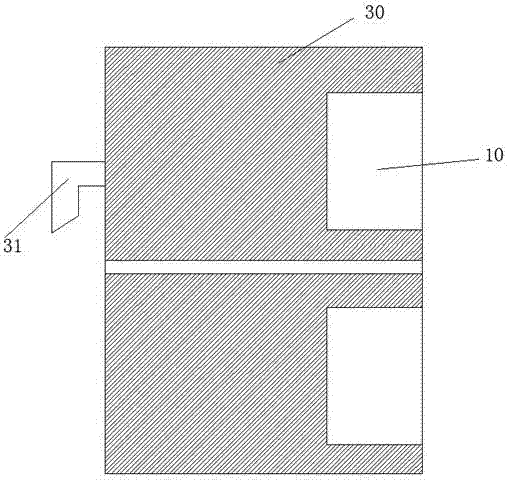
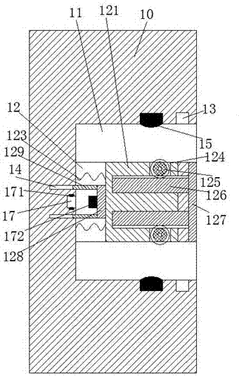
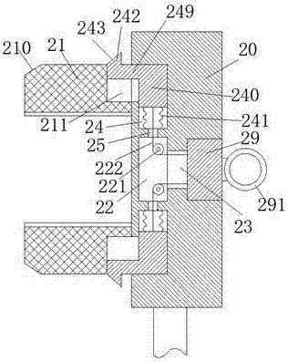
[0021] Such as Figure 1 to Figure 5 As shown, a dust collector device of the device of the present invention includes a cabinet 30 and an electrical connector 20 connected to the dust collector. The left side of the cabinet 30 is provided with a hook 31 corresponding to the front and back, and the hook 31 is used for The suspension of the cabinet 30 is fixed so as to reduce the occupied area. There are at least two sets of electrical connect...


PUM


Abstract

The invention discloses a dust remover device. The dust remover device comprises a machine cabinet and an electric connector connected with a dust remover. The left side face of the machine cabinet isforwards and backwards correspondingly provided with a hook component. The machine cabinet is upwards and downwards separately provided with at least two groups of electric bases matched with the electric connector. Each of the electric bases is upwards and downwards correspondingly provided with a jack socket of which the opening faces to the right. A sliding cavity communicated with two jack sockets is installed between two jack sockets. A sliding frame is leftwards and rightwards slidably installed in the sliding cavity. The right end face, positioned between two jack sockets, of the electric base is further provided with a hollow groove. An ejection arm is installed in the hollow groove. The right end wall of the sliding cavity is upwards and downwards correspondingly provided with athrough groove communicated with the hollow groove mutually. The sliding frame is upwards and downwards correspondingly provided with a first sliding channel of which the opening faces to the throughgroove. A sliding bar is slidably installed in the first sliding channel. The right end of the sliding bar passes through the through groove and is fixedly connected with the ejection arm.

Description

technical field [0001] The invention relates to the field of dust collectors, in particular to a dust collector device. Background technique [0002] Industrial dust collectors are widely used in industrial production. However, industrial dust collectors have relatively high power. In some factories, power supply cabinets are specially equipped for plugging and power supply of dust collectors. There are electric connection blocks in the power supply cabinets. However, these electric connection blocks are set The mode is single, and the internal conductive sheet is set relatively outside. This conductive sheet is easily touched by the metal sheet or metal rod. Therefore, when people who lack safety awareness insert the metal rod into the electrical socket, it is easy to get an electric shock. In addition, the traditional dust collector is extremely unstable when it is connected to the power supply. If you accidentally kick the electric connector or trip over the wire, it will...

Claims


Application Information

Patent Timeline
IPC IPC(8): H01R13/447H01R13/627H01R13/703
Inventor 王晨亮
Owner 王晨亮
Why Eureka
Try Eureka