Al technical title is built by PatSnap Al team. It summarizes the technical point description of the patent document.
A technology of dust removal device and dust removal chamber, which is applied in combination device, separation method, dispersed particle separation, etc., can solve the problems of large power consumption, high price and incomplete dust removal, etc., to achieve convenient operation, improve use effect, simple structure
Pending Publication Date: 2018-01-16
NANJING LISHUI LIHUA SPRING FACTORY
View PDF12 Cites 13 Cited by
Summary
Abstract
Description
Claims
Application Information
AI Technical Summary
This helps you quickly interpret patents by identifying the three key elements:
Problems solved by technology
Method used
Benefits of technology
Problems solved by technology
There are 21 major categories and more than 1,600 varieties of spring products, mainly including valve springs, suspension springs, diaphragm springs, shock absorbing springs, hydraulic springs, oil pump springs, disc springs, high-temperature springs, retaining springs, and extension springs. , torsion springs, compression springs, scroll springs, and heterosexual springs, etc., springs are prone to produce a large amount of metal dust in the process of production, but the price of the existing spring production dust removal device is high, and the normal work consumes a lot of power. There are also many supporting equipment, and the existing spring production dust removal device is not thorough in dust removal, and it is troublesome to clean the dust
Method used
Image
Click on the blue label to locate the original text in one second.
Reading with bidirectional positioning of images and text.
Examples
Embodiment Construction
[0019] In order to make the technical means, creative features, goals and effects achieved by the present invention easy to understand, the present invention will be further described below in conjunction with specific embodiments.
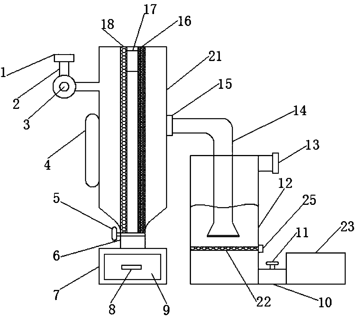
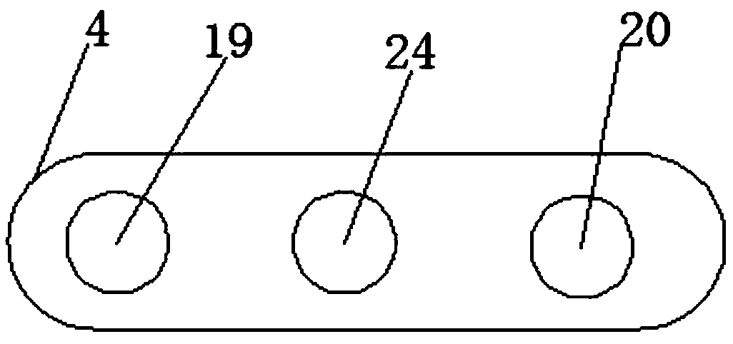
[0020] like Figure 1-3 As shown, a dust removal device for spring production includes a dust removal chamber 21, a dust collecting hopper 7 and an air inlet 1, the bottom of the air inlet 1 is provided with an air inlet pipe 2, and the air inlet pipe 2 is provided with a blower 3 , the air inlet pipe 2 runs through the blower 3, one end of the air inlet pipe 2 is connected to the dust removal chamber 21, the left middle part of the dust removal chamber 21 is provided with a control panel 4, and the left and right sides of the top of the dust removal chamber 21 are respectively provided with a second A filter screen 18 and a second filter screen 16, the bottom of the dust removal chamber 21 is provided with an ash outlet 6, the ash outlet 6 is pro...
PUM
Abstract
The invention discloses a dust removal device for spring production. The dust removal device comprises a dust removal chamber, a dust collection hopper and an air inlet, wherein an air inlet pipe is arranged at the bottom of the air inlet; an air blower is arranged on the air inlet pipe; the air inlet pipe penetrates through the air blower; one end of the air inlet pipe is connected with the dustremoval chamber; a control panel is arranged at the left middle of the dust removal chamber; a first filter screen and a second filter screen are arranged on the left and right sides of the top of thedust removal chamber respectively; a dust falling port is formed in the bottom of the dust removal chamber; a valve A is arranged on the dust falling port; an air outlet is formed in the middle of the right side of the dust removal chamber. According to the dust removal device disclosed by the invention, relatively large metal dust particles are subjected to primary filtration through the firstfilter screen and the second filter screen in the dust removal chamber; adsorption settlement is formed at the moment of sufficient contact between metal dust and water through a water storage tank atone end of the air guide pipe, thus, thorough removal of the metal dust is facilitated, the using effect of the dust removal effect is improved, and the dust removal device is relatively practical and suitable for wide popularization and application.
Description
technical field [0001] The invention relates to a dust removal device, in particular to a dust removal device for spring production. Background technique [0002] At present, as an important component in industrial systems, springs are used in a large amount and there are various types. Therefore, the production of springs is originally handmade and gradually moves toward automation. There are 21 major categories and more than 1,600 varieties of spring products, mainly including valve springs, suspension springs, diaphragm springs, shock absorbing springs, hydraulic springs, oil pump springs, disc springs, high-temperature springs, retaining springs, and extension springs. , torsion springs, compression springs, scroll springs, and heterosexual springs, etc., springs are prone to produce a large amount of metal dust in the process of production, but the price of the existing spring production dust removal device is high, and the normal work consumes a lot of power. There ar...
Claims
Application Information
Patent Timeline
Application Date:The date an application was filed.
Publication Date:The date a patent or application was officially published.
First Publication Date:The earliest publication date of a patent with the same application number.
Issue Date:Publication date of the patent grant document.
PCT Entry Date:The Entry date of PCT National Phase.
Estimated Expiry Date:The statutory expiry date of a patent right according to the Patent Law, and it is the longest term of protection that the patent right can achieve without the termination of the patent right due to other reasons(Term extension factor has been taken into account ).
Invalid Date:Actual expiry date is based on effective date or publication date of legal transaction data of invalid patent.