
A Method and Device Based on Friction Stir Bonding-Microdroplet Composite Additive Manufacturing

A technology of friction stir and additive manufacturing, which is applied in the field of metal material manufacturing, can solve problems such as deformation fusion, defects, and cracks, and achieve the effects of improved bonding performance, small thermal deformation, and simple processing procedures

Active Publication Date: 2019-02-12
NANJING UNIV OF AERONAUTICS & ASTRONAUTICS
View PDF3 Cites 0 Cited by
  • Summary
  • Abstract
  • Description
  • Claims
  • Application Information

AI Technical Summary

Problems solved by technology

[0007] The purpose of the present invention is to address defects such as pores, spheroidization, cracks, deformation, and poor fusion of metal products produced by existing high-energy beam additive manufacturing and metal droplet injection technology, and to improve material properties by combining friction stir joining technology The characteristics of the invention, an additive manufacturing method based on friction stir bonding-micro droplet composite, and provide a corresponding device at the same time

Method used


Image

  • A Method and Device Based on Friction Stir Bonding-Microdroplet Composite Additive Manufacturing

Examples


Embodiment 1

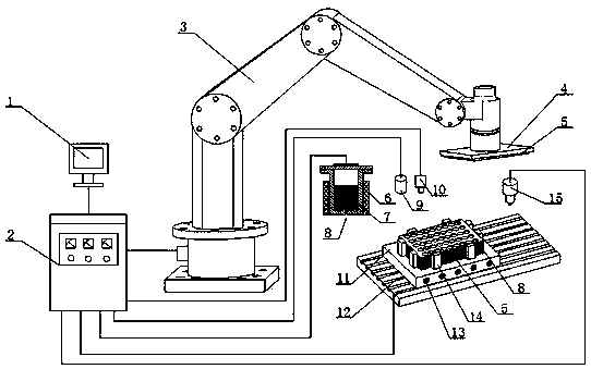
[0031] Such as figure 1 shown.

[0032] A method based on friction stir bonding-microdroplet composite additive manufacturing, the specific steps are as follows:

[0033] (1) According to the three-dimensional model of the required additive manufacturing parts, the parts are divided into several layers by slicing method, from bottom to top, respectively recorded as the 1st, 2nd, 3rd, ..., n layers, among which the odd numbered layers Metal sheets are used, and the even-numbered layers are made of micro-droplet layers for additive manufacturing. The first layer of metal sheets 5 is placed on the substrate 11, and the fixture system is started to fix the first layer of metal sheets 5. The substrate 11 is fixed on the five-axis by bolts. On the CNC workbench 12.

[0034] (2) Control the temperature of the micro-droplet injection system 6 through the computer 1 to melt the metal into molten metal 7, start the auxiliary heating device 13 and the ultrasonic vibration device 10, an...

Embodiment 2

[0038] Such as figure 1 shown.

[0039] A friction stir bonding-microdroplet composite additive manufacturing device includes a control system, a fixture system, a metal sheet conveying system, a microdroplet injection system, and a friction stir bonding system. Such as figure 1 As shown, the control system is composed of a computer 1 and a controller 2; the fixture system is composed of a base plate 11, an ultrasonic vibration device 10, an auxiliary heating device 13 and a plurality of clamps 14; the sheet metal conveying system is composed of The mechanical arm 3, the adsorption device 4 and the positioning device 9 are composed of the micro-droplet injection system, which is composed of the micro-droplet injection device 6, the molten metal 7 and the micro-droplet 8; The CNC workbench 12 and the horizontal friction stir device 15 are composed. The ultrasonic vibration device 10 is located directly above the substrate, and its spatial position can be controlled by the co...


PUM


Abstract

A composite additive manufacturing method based on stirring frictional connection-micro molten drops is characterized by comprising the following steps that 1, a three-dimensional model of a part to be machined is manufactured according to required additional materials, a slicing method is adopted to divide the part into a plurality of layers, and a first layer of metal plates is put on a base plate; 2, the temperature of a micro molten drop spraying system is controlled through a computer to melt metal into molten metal, and micro molten drops are sprayed on the first layer of metal plates; 3, a second layer of metal plates is put at a required position, a clamp system is started, the second layer of metal plates is clamped on the micro molten drop layer, and a stirring friction device isadopted to perform stirring frictional connection of plates-micro molten drop layer-plates according to a predetermined trajectory; 4, after stirring frictional connection is completed, the steps 2 and 3 are repeated, and layer-by-layer accumulation and manufacturing of the metal plates and the micro molten drop layer are achieved. The composite additive manufacturing method is simple in treatment process and easy to carry out.

Description

technical field [0001] The present invention relates to a metal material manufacturing technology, in particular to a metal material additive manufacturing technology, in particular to a friction stir bonding-microdroplet composite additive manufacturing method and device. Background technique [0002] Additive Manufacturing (AM) technology is a technology that uses the method of gradually accumulating materials to manufacture solid parts. Compared with the traditional material removal-cutting technology, it is a "bottom-up" manufacturing method. [0003] There are many methods of additive manufacturing. High-energy beam (laser beam, electron beam) additive manufacturing technology is an important development direction in this technical field. It is a combination of high-energy beam and CAD / CAM technology. In an environment where metal wires or metal powders are fed to the focused heating zone, the materials are melted layer by layer, solidified and piled up to form a direct...

Claims


Application Information

Patent Timeline
Patent Type & Authority Patents(China)
IPC IPC(8): B22F3/115B23K20/12B23K20/10B33Y10/00B33Y30/00
Inventor 左立生左敦稳朱永成叶赵伟侯源君郭燕
Owner NANJING UNIV OF AERONAUTICS & ASTRONAUTICS
Learn More