Bottle blowing machine provided with clamping mechanism

A technology of clamping mechanism and bottle blowing machine, which is applied in the field of bottle blowing, can solve problems such as hidden dangers in operation stability and complex motion trajectory of manipulator, and achieve the effects of reducing design difficulty, reducing tracking stroke, and simplifying motion trajectory

Pending Publication Date: 2018-01-16
JIANGSU NEWAMSTAR PACKAGING MACHINERY
View PDF5 Cites 2 Cited by
  • Summary
  • Abstract
  • Description
  • Claims
  • Application Information

AI Technical Summary

Problems solved by technology

As a result, the movement trajectory of the manipulator is more complicated, and there are hidden dangers in the operation stability.

Method used


Image

  • Bottle blowing machine provided with clamping mechanism
  • Bottle blowing machine provided with clamping mechanism
  • Bottle blowing machine provided with clamping mechanism

Examples


Embodiment Construction

[0017] The technical solution of the present invention will be further described below in conjunction with the accompanying drawings.

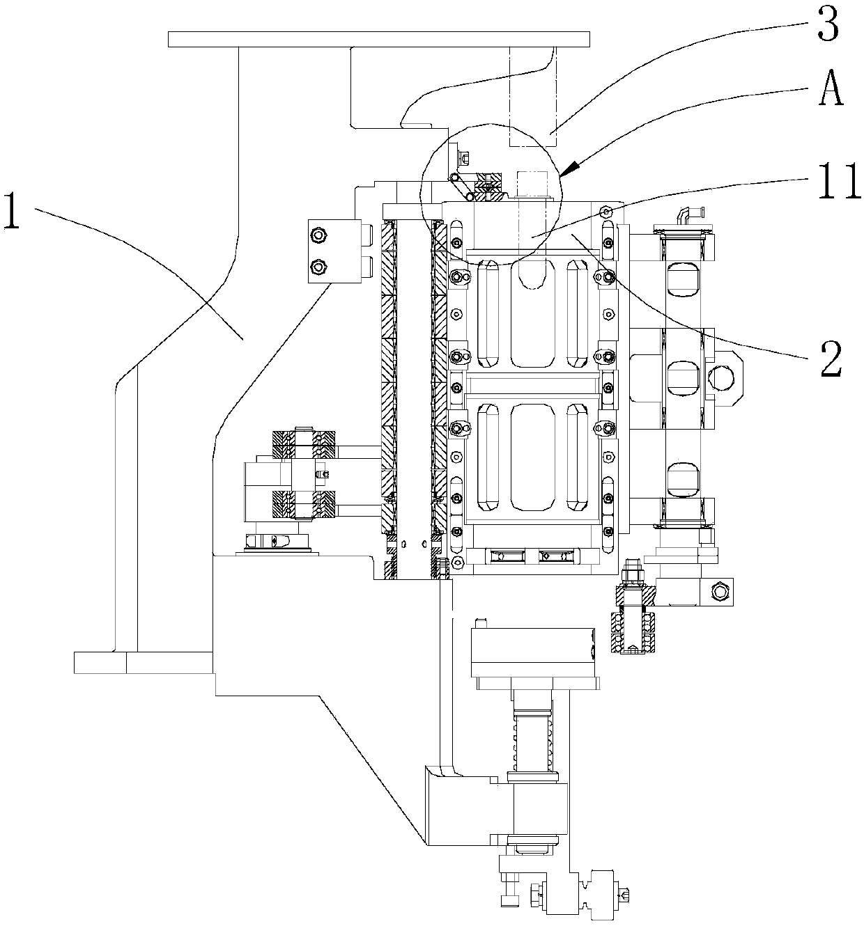
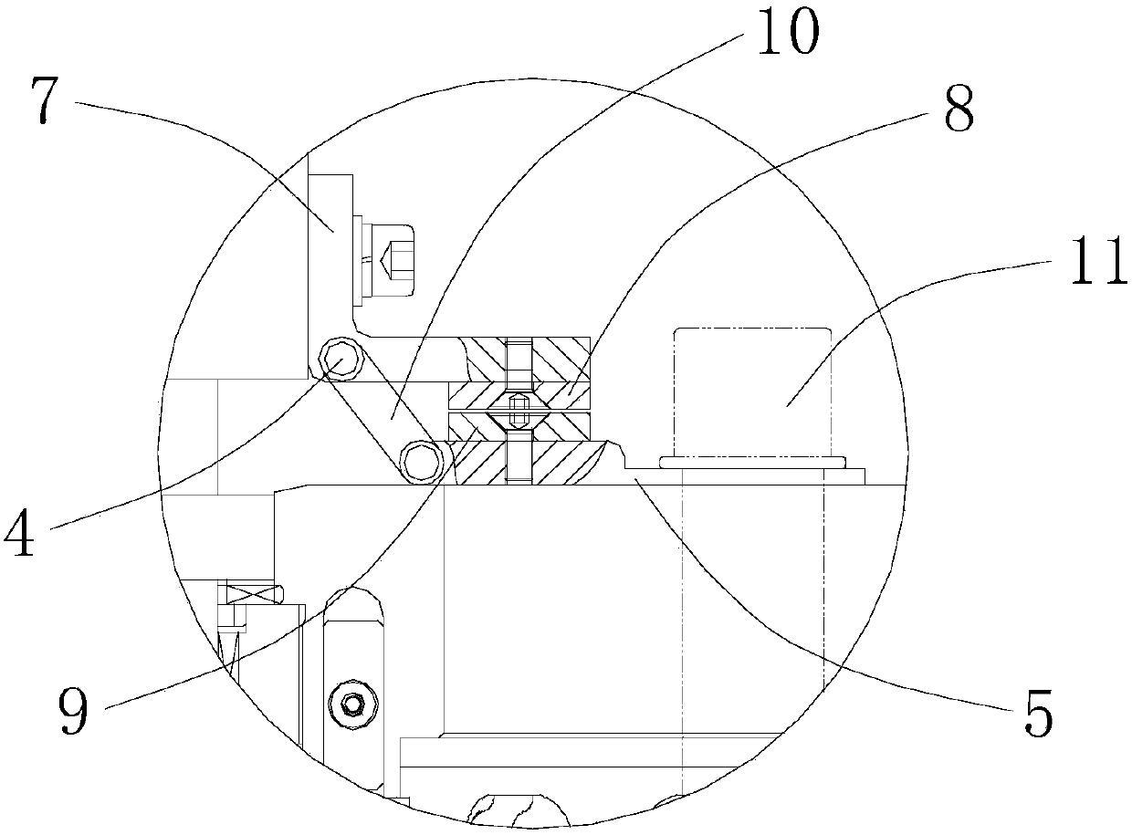
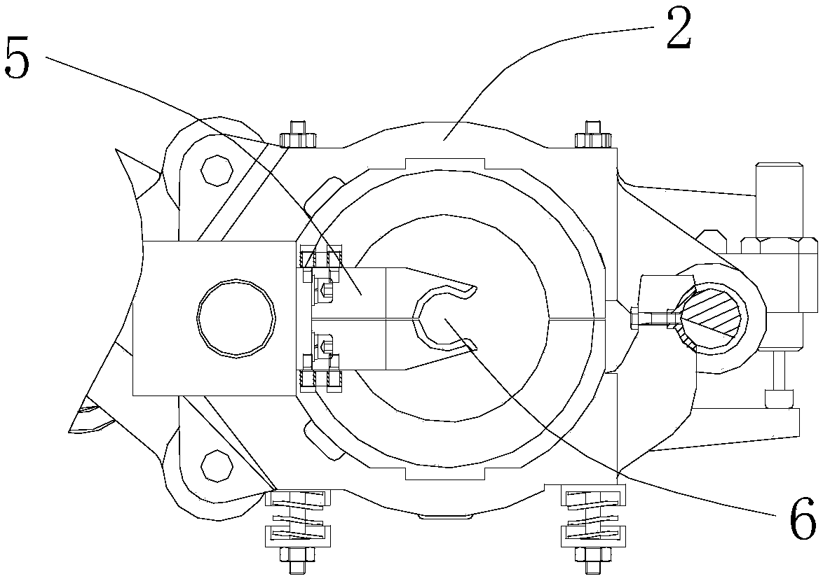
[0018] see Figure 1-3 As shown, the above-mentioned bottle blowing machine with a clamping mechanism includes a frame 1, an opening and closing mold frame 2 arranged on the frame 1, and a mold frame located on the frame 1 that moves up and down in the vertical direction. The sealing mechanism 3 above the opening and closing mold frame 2 is described above. In this embodiment, the sealing mechanism 3 is also used to blow compressed air into the bottle blank 11 .

[0019] The clamping mechanism includes a clamping part 5 which is arranged on the frame 1 with one end rotating around the horizontal axis 4, and the clamping part 5 is located between the sealing mechanism 3 and the opening and closing mold frame 2 in the vertical direction. In this embodiment, the clamping member 5 is around its left end (see figure 2 as shown, figure 2 The le...


PUM


Abstract

The invention discloses a bottle blowing machine provided with a clamping mechanism. The bottle blowing machine comprises a rack, a die opening and closing die-set arranged on the rack and a sealing mechanism which is vertically movable, arranged on the rack and located above the die opening and closing die-set, wherein the clamping mechanism comprises a clamping assembly and a driving device, oneend of the clamping assembly rotates around a horizontal shaft, the clamping assembly is arranged on the rack and located between the sealing mechanism and the die opening and closing die-set, the driving device is arranged on the rack and used for driving the clamping assembly to rotate around the horizontal shaft to be away from the die opening and closing die-set, and a notch for clamping a bottle preform is formed in the other end of the clamping assembly and located under the sealing mechanism. According to the bottle blowing machine provided with the clamping mechanism, the clamping assembly for clamping the bottle preform and the driving device for driving the clamping assembly to be away from the die opening and closing die-set are arranged on the rack, tracking travel of a manipulator is reduced, motion trail of the manipulator is simplified, and operating stability of the manipulator is improved; design difficulty of a manipulator cam is reduced; assistant time for preform feeding and bottle taking is shortened, and single-capacity productivity can be improved effectively.

Description

technical field [0001] The invention relates to the technical field of bottle blowing, in particular to a bottle blowing machine with a clamping mechanism. Background technique [0002] When the bottle blowing machine is blowing the bottle, the preform needs to be clamped and transported to the mold by the robot, and then blown. When the manipulator transports the preform, it needs to track the movement trajectory of the mold, and the manipulator can only leave after the mold is completely closed. Similarly, when the blown bottle needs to be taken out of the mold through the clamping of the manipulator, the manipulator needs to clamp the bottle mouth and track the movement trajectory of the mold before the mold is opened, and the manipulator can only leave after the mold is completely opened. As a result, the movement trajectory of the manipulator is relatively complicated, and there are hidden dangers in the operation stability. Contents of the invention [0003] The ob...

Claims


Application Information

Patent Timeline
Patent Type & Authority Applications(China)
IPC IPC(8): B29C49/56B29C49/70B29C49/42
Inventor 沈军叶鹏周卫林
Owner JIANGSU NEWAMSTAR PACKAGING MACHINERY
Why Eureka
Try Eureka