Pan-tilt device and unmanned aerial vehicle

A technology of unmanned aerial vehicle and gimbal, applied in the field of unmanned aerial vehicle, can solve the problems of picture jitter marks, inflexible shooting, unreasonable structure, etc., to achieve the effect of reasonable structure, good shooting effect, and real-time angle adjustment

Pending Publication Date: 2018-01-16
SHENZHEN GOODRONE INTELLIGENT TECH CO LTD
View PDF1 Cites 3 Cited by
  • Summary
  • Abstract
  • Description
  • Claims
  • Application Information

AI Technical Summary

Problems solved by technology

Although the pan-tilt frame device of the invention realizes the function of fixing the camera, the invention also has the problems of inflexibility when shooting, unsightly appearance and unreasonable structure
[0005] At the same time, the existing gimbal mainly adopts two-axis or three-axis mechanic

Method used


Image

  • Pan-tilt device and unmanned aerial vehicle
  • Pan-tilt device and unmanned aerial vehicle
  • Pan-tilt device and unmanned aerial vehicle

Examples


Example Embodiment

[0027] The specific embodiments of the present invention will be described in further detail below with reference to the accompanying drawings.

[0028] In the description of the present invention, it should be understood that the terms "length", "width", "upper", "lower", "front", "rear", "left", "right", "vertical", The orientation or positional relationship indicated by "horizontal", "top", "bottom", "inner", "outer", etc. is based on the orientation or positional relationship shown in the drawings, and is only for the convenience of describing the present invention and simplifying the description, not It indicates or implies that the pointed device or element must have a specific orientation, be constructed and operated in a specific orientation, and therefore cannot be understood as a limitation of the present invention.

[0029] In addition, the terms "first" and "second" are only used for descriptive purposes, and cannot be understood as indicating or implying relative impor...


PUM


Abstract

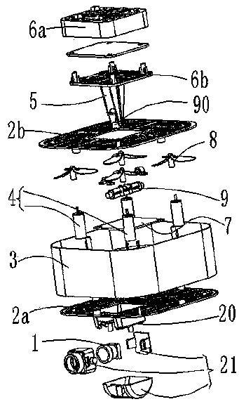
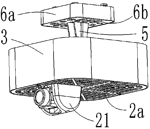
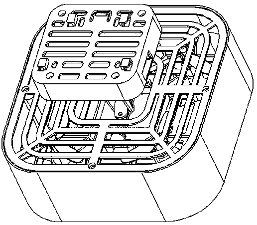
The invention discloses a pan-tilt device and an unmanned aerial vehicle. The pan-tilt device comprises a rack assembly, an adjusting assembly, a shooting device and a control assembly. The control assembly comprises a circuit board, a connection wire, a processor and an inertial sensor, wherein the inertial sensor is used for detecting posture information of the shooting device, and the processorcontrols the adjusting assembly according to the posture information; and the adjusting assembly comprises a universal connector for connecting the rack assembly with the shooting device, and an adjusting device for adjusting the shooting angle of the shooting device. The unmanned aerial vehicle comprises an unmanned aerial vehicle body. The pan-tilt device is connected to the lower portion of the unmanned aerial vehicle body in a buckled mode, and the unmanned aerial vehicle body is electrically connected with the pan-tilt device. By adjusting the angle of the shooting device through spiralwings, the angle can be adjusted in real time, and adjustment is more flexible. Meanwhile, the design structure is more reasonable, the angle is adjusted more conveniently in use, and the shooting effect is better compared with a traditional pan-tilt.

Description

technical field [0001] The invention belongs to the technical field of unmanned aerial vehicles, and relates to a pan-tilt device and an unmanned aerial vehicle. Background technique [0002] With the improvement of the automation of line inspection, line inspection drones are widely used. In order to facilitate the carrying of detection equipment, it is necessary to install a pan-tilt frame device on the line inspection drone, so the cloud for line inspection drones The platform frame device is an important part. In the existing pan-tilt frame device used for line inspection drones, especially small electric pan-tilts, a fixed link is formed between the load plate, the installation frame and the body, and the body is easy to vibrate. Transmission to the load section affects the load imaging effect. At the same time, because the gimbal frame is directly fixed to the body, it is not conducive to the standardization of various small UAVs or multiple installation methods. [0...

Claims


Application Information

Patent Timeline
IPC IPC(8): B64D47/08
Inventor 伍勇
Owner SHENZHEN GOODRONE INTELLIGENT TECH CO LTD
Why Eureka
Try Eureka