
Local electroplating apparatus of mold

A local electroplating and mold technology, applied in the electrolysis process, electrolysis components, cells, etc., can solve the problems of high labor intensity, complicated process, reduction of electroplating effect and electroplating efficiency, etc.

Inactive Publication Date: 2018-01-16
苏州特精模具有限公司
View PDF0 Cites 3 Cited by
  • Summary
  • Abstract
  • Description
  • Claims
  • Application Information

AI Technical Summary

Problems solved by technology

Ordinary local electroplating equipment needs to conduct pre-insulation treatment on the local area of ​​the mold, the process is complicated and labor-intensive
At the same time, as the concentration of the electroplating solution decreases, the electroplating effect and efficiency decrease, and manual replacement of the electroplating solution is time-consuming and laborious.

Method used


Image

  • Local electroplating apparatus of mold
  • Local electroplating apparatus of mold

Examples


Embodiment

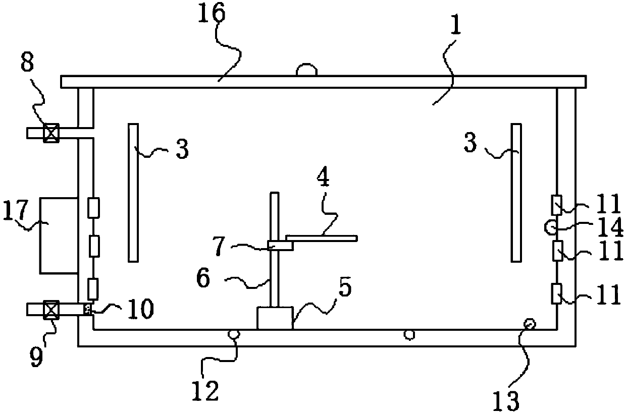
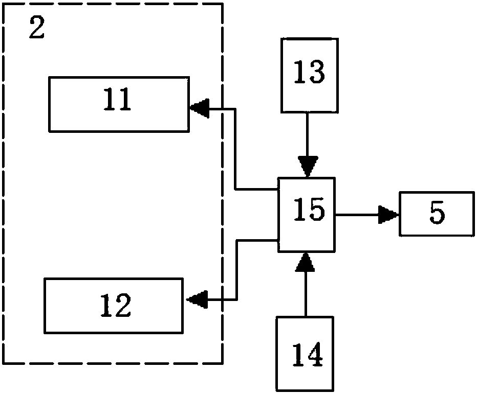
[0026] Example: A partial electroplating device for a mold, such as figure 1 with figure 2 As shown, it includes an electroplating tank 1, a heater 2, an anode conductive rod 3, and a cathode conductive seat 4. The heater, the anode conductive rod and the cathode conductive seat are all located in the electroplating tank, and the electroplating tank There is a driving unit at the bottom and inside of the cathode conductive base to drive the cathode conductive base up and down;

[0027] The drive unit includes a motor 5, a lead screw 6 and a slider 7. The output shaft of the motor is connected to the lead screw, and the slider is sleeved on the lead screw and is driven by the motor. The lead screw moves up and down, the cathode conductive seat is installed on the slider, and the cathode conductive seat is installed with a clamp for placing a mold, and the clamp is a hollow clamp;

[0028] A liquid injection valve 8 is installed at the upper end of one side of the electroplating ta...


PUM


Abstract

The invention discloses a local electroplating apparatus of a mold. The local electroplating apparatus comprises an electroplating bath, a heater, an anode conductive rod and a cathode conductive seat, wherein the bottom and the inner side of the electroplating bath are provided with a drive unit for driving the cathode conductive seat to lift up and down; the drive unit comprises a motor, a leadscrew and a slide block, the slide block sleeves the lead screw, the cathode conductive seat is installed on the slide block, the cathode conductive seat is provided with a clamp for storing the mold,the upper end of one side of the electroplating bath is provided with a liquid injection valve, the lower end of the electroplating bath is provided with a liquid discharging valve, and a filter netis disposed on the upstream of the liquid discharging valve in the electroplating bath; and the local electroplating apparatus also comprises a concentration sensor, a liquid level sensor and a PLC controller. By adopting the local electroplating apparatus, the automatic local electroplating of the mold can be realized, the concentration of an electroplating solution can be detected in real time,the electroplating solution can be automatically replaced, the thickness of a plating layer is uniform, the appearance and the mechanical performance of the local plating layer of the mold are ideal,and the strength and appearance of the mold can be improved.

Description

Technical field [0001] The invention relates to the technical field of mold production and processing equipment, in particular to a mold partial electroplating device. Background technique [0002] Molds, various molds and tools used in industrial production to obtain desired products by injection molding, blow molding, extrusion, die-casting or forging molding, smelting, stamping and other methods. In order to improve the performance of the mold, the mold is often electroplated. However, some areas of the mold do not require electroplating. In order to reduce costs, partial electroplating is usually used. Ordinary partial electroplating equipment requires pre-insulation treatment on the partial area of ​​the mold, which is complicated and labor-intensive. At the same time, as the concentration of the electroplating solution decreases, the electroplating effect and efficiency are reduced, and manual replacement of the electroplating solution takes time and effort. Therefore, t...

Claims


Application Information

Patent Timeline
Patent Type & Authority Applications(China)
IPC IPC(8): C25D5/02C25D17/00C25D21/12
Inventor 付朝黄荣利郭宁州
Owner 苏州特精模具有限公司
Learn More