
Wear-resistant hooking lock for point rails of external-locking turnout

A turnout and anti-wear technology, applied in roads, tracks, buildings, etc., can solve the problems of excessive waste of equipment resources, changes in size wear, wear of lock hooks and core rails, etc., to save resources, reduce replacement times, reduce The effect of the number of maintenance replacements

Inactive Publication Date: 2018-01-16
张振坤 +2
View PDF9 Cites 0 Cited by
  • Summary
  • Abstract
  • Description
  • Claims
  • Application Information

AI Technical Summary

Problems solved by technology

[0002] The locking hook of the core rail driven by the outer locking switch of the railway is to block the bottom two sides of the core rail by the U-shaped opening in the middle of the lock hook, and the lock hook is driven by the switch machine to pull the switch locking rod to bring the core rail to the core rail. The basic rails on both sides of the rail are closely attached and separated, because the U-shaped opening in the middle of the lock hook is fixed. Under normal circumstances, the U-shaped opening in the middle of the lock hook can keep in parallel with the bottom surface of the core rail. However, as the use Over time, the contact surface between the U-shaped opening in the middle of the lock hook and the bottom of the basic rail will be worn, which will change the size of the end surface of the U-shaped opening in the middle of the lock hook, and also cause the contact surface at the bottom of the core rail to wear and form a concave shape. If the core rail crawls due to various external reasons, the end face of the U-shaped opening on the lock hook may not necessarily come into contact with the worn concave opening on the bottom of the core rail at the origin to cause misalignment, so that the switch is closely attached. Finally, the vibration generated when the train passes through the switch is likely to cause the contact surface of the U-shaped opening on the lock hook to slide into the concave opening at the bottom of the core rail, so that the contact pressure between the lock hook and the core rail will be reduced. The change will cause a gap between the core rail and the basic rail, which will seriously endanger the driving safety
Furthermore, if the torsion angle is generated due to the crawling of the core rail or the crawling offset of the lock hook with the basic rail, the two ends of the U-shaped opening in the middle of the lock hook cannot keep in plane contact with the core rail, and serious wear will occur between the lock hook and the core rail. , either the wear size of the lock hook changes, or the core rail wears into a concave opening, and both the core rail and the lock hook must be replaced. This is indeed a huge challenge for a set of core rails worth nearly one million Loss, whether it is to replace the lock hook or the core rail, is also a very troublesome task. Not only does the workload take a long time, but the key is to bring many unstable factors to the use of the equipment and affect the driving, and it also wastes too much equipment resources.

Method used


Image

  • Wear-resistant hooking lock for point rails of external-locking turnout
  • Wear-resistant hooking lock for point rails of external-locking turnout
  • Wear-resistant hooking lock for point rails of external-locking turnout

Examples


Embodiment Construction

[0027] specific implementation plan

[0028] In order to further understand the content, characteristics and effects of the present invention, the following embodiments are listed hereby, and are described in detail in conjunction with the accompanying drawings as follows:

[0029] Such as figure 1 , figure 2 , image 3 , Figure 4 , Figure 5 , Image 6 , Figure 7 , Figure 8 , Figure 9 Shown, the present invention is made of lock hook (1) and anti-wear block (2) and bearing pin (3), buckle plate (4), bolt pin (5), bolt ( 6) is formed, the two ends of the U-shaped mouth (1-2) in the middle part of the lock hook (1) are respectively equipped with anti-wear blocks (2) along the arc surface (1-3), and the two pin shafts (3) pass through the two pins respectively. The waist-shaped hole (2-3) vertically through of a wear-resistant block (2) is screwed in the threaded hole (1-4) on the bottom plane at the two ends of the U-shaped mouth (1-2), and the two buckle plates (...


PUM


Abstract

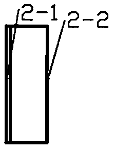
A wear-resistant hooking lock for point rails of an external-locking turnout mainly consists of a hooking lock (1), wear-resistant blocks (2) and pin shafts (3) arranged at both ends of a U-shaped opening at the middle of the hooking lock, fastening and pressing plates (4), pin bolts (5) and bolts (6). The wear-resistant blocks (2) are respectively mounted along cambered surfaces (1-3) at both ends of the U-shaped opening (1-2) at the middle of the hooking lock (1). When planes (2-1) of the wear-resistant blocks (2) are in close contact with bottom surfaces of the point rails and stressed to generate torsion angles, cambered surfaces (2-2) of the wear-resistant blocks (2) can automatically rotate along the vertical cambered surfaces (1-3) at both ends of the U-shaped opening (1-2), so thatthe planes (2-1) of the wear-resistant blocks (2) can be always in plane contact with the bottom surfaces of the point rails and the wear of the hooking lock to the point rails is reduced. When the size of the wear-resistant blocks (2) on the hooking lock changes because of the wear during the using process and is not in conformity with the requirements, the excessively worn wear-resistant blocks(2) which are arranged at both ends of the U-shaped opening of the hooking lock can be replaced quickly and conveniently to recover a standard state of the hooking lock, so that the safety performance of equipment and the reliability for use are improved and the disturbance to the running of trains is reduced.

Description

Technical field: [0001] The invention relates to an anti-wear core rail lock hook on an external lock switch, which is especially suitable for the matched connection between the core rail and the lock hook on the speed-increasing railway switch. Background technique: [0002] The locking hook of the core rail driven by the outer locking switch of the railway is to block the bottom two sides of the core rail by the U-shaped opening in the middle of the lock hook, and the lock hook is driven by the switch machine to pull the switch locking rod to bring the core rail to the core rail. The basic rails on both sides of the rail are closely attached and separated, because the U-shaped opening in the middle of the lock hook is fixed. Under normal circumstances, the U-shaped opening in the middle of the lock hook can keep in parallel with the bottom surface of the core rail. However, as the use Over time, the contact surface between the U-shaped opening in the middle of the lock hoo...

Claims


Application Information

Patent Timeline
Patent Type & Authority Applications(China)
IPC IPC(8): E01B7/00
Inventor 张振坤石立祥王勇
Owner 张振坤
Learn More