Bridge building equipment

A technology for construction equipment and bridges, which is applied in bridge construction, bridges, buildings, etc. It can solve problems such as power failure of electrical facilities, disconnection of electrical connectors, and different lengths of energized lines, so as to achieve increased stability, increased use safety, and simple operation convenient effect

Active Publication Date: 2018-01-16
南京浦口科创投资集团有限公司
View PDF5 Cites 6 Cited by
  • Summary
  • Abstract
  • Description
  • Claims
  • Application Information

AI Technical Summary

Problems solved by technology

[0002] In the process of bridge building construction, the use of electrical facilities is inseparable. The use of electrical facilities is to directly penetrate the electrical connectors connected to them into the electrical connection frame to connect to the power supply. This plug-in fit method is more convenient to operate, but the length of the energized line between the electrical connector and the electrical equipment is different, and there is no other locking device to lock the electrical connector after the electrical connector penetrates into the electrical connection frame. When kicked, it will cause the electrical connector to be separated from the electrical socket, resulting in a sudden power failure of the electrical facility

Method used


Image

  • Bridge building equipment
  • Bridge building equipment
  • Bridge building equipment

Examples


Embodiment Construction

[0020] The preferred embodiments of the present invention will be described in detail below in conjunction with the accompanying drawings, so that the advantages and features of the present invention can be more easily understood by those skilled in the art, so as to define the protection scope of the present invention more clearly.

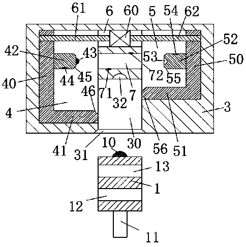
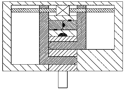
[0021] refer to Figure 1-4 The shown bridge construction equipment includes an electrical connector 1 connected to electrical equipment through a line 11 and a main frame 100. The connecting frame 3, the front end surface of the electric connecting frame 3 is provided with a slot 30, and the slot 30 is used for the penetration and connection of the electric connector 1, and the center of the rear end surface of the electric connector 1 is provided with a first electric Connecting pin 10, the front and rear locking holes 12 and the rear locking holes 13 of the electrical connector 1 are arranged in the front and back of the electrical connector 1...


PUM


Abstract

The invention discloses bridge building equipment. The bridge building equipment comprises an electric connector connected with an electric equipment facility through a line, and a main frame, whereina bottom plate is fixedly mounted on the bottom end surface of the main frame, and a plurality of electric connecting frames are arranged in the main frame; a slot is formed in the front end surfaceof each electric connecting frame, and is used for allowing the electric connector to penetrate through for cooperating connection; a first electric connecting pin is arranged in the center of the rear end surface of the electric connector; a front keyhole and a rear keyhole which are in front-and-back equal arrangement and separately penetrate through the electric connector in a left-and-right manner are formed in the electric connector; a first electric connecting hole in cooperating connection with the first electric connecting pin is formed in the center of the rear end wall of each slot;and a left sliding hole which communicates with the corresponding slot is formed in the left end wall of each slot, a right sliding hole which communicates with the corresponding slot is formed in theright end wall of each slot, and each left sliding hole and the corresponding right sliding hole are oppositely formed. According to the bridge building equipment disclosed by the invention, lockingand unlocking of the electric connector can be completed through a driving machine, and electrifying and power failure of the first electric connecting hole can also be completed; the operation is simple and convenient; and during building construction, the bridge is safer and stabler, and the electricity supply stability is good.

Description

technical field [0001] The invention relates to the field of bridges, in particular to bridge construction equipment. Background technique [0002] In the process of bridge building construction, the use of electrical facilities is inseparable. The use of electrical facilities is to directly penetrate the electrical connectors connected to them into the electrical connection frame to connect to the power supply. This plug-in fit method is more convenient to operate, but the length of the energized line between the electrical connector and the electrical equipment is different, and there is no other locking device to lock the electrical connector after the electrical connector penetrates into the electrical connection frame. When it is kicked, it will cause the electrical connector to be separated from the electrical socket, thereby causing a sudden power failure of the electrical facility. Contents of the invention [0003] The technical problem to be solved by the presen...

Claims


Application Information

Patent Timeline
Patent Type & Authority Applications(China)
IPC IPC(8): E01D21/00H01R13/629H01R13/639
Inventor 王赛飞
Owner 南京浦口科创投资集团有限公司
Why Eureka
Try Eureka