Ripple baseplate detachable anti-flood wall
A flood control wall and bottom plate technology, applied in dikes, door/window protection devices, coastline protection, etc., can solve the problems of temporary construction and dismantling difficulties, poor use effect, difficult operation, etc., and achieve convenient and fast installation and dismantling operations Effect
- Summary
- Abstract
- Description
- Claims
- Application Information
AI Technical Summary
Problems solved by technology
Method used
Image
Examples
Embodiment 1
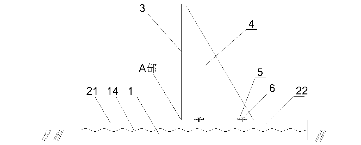
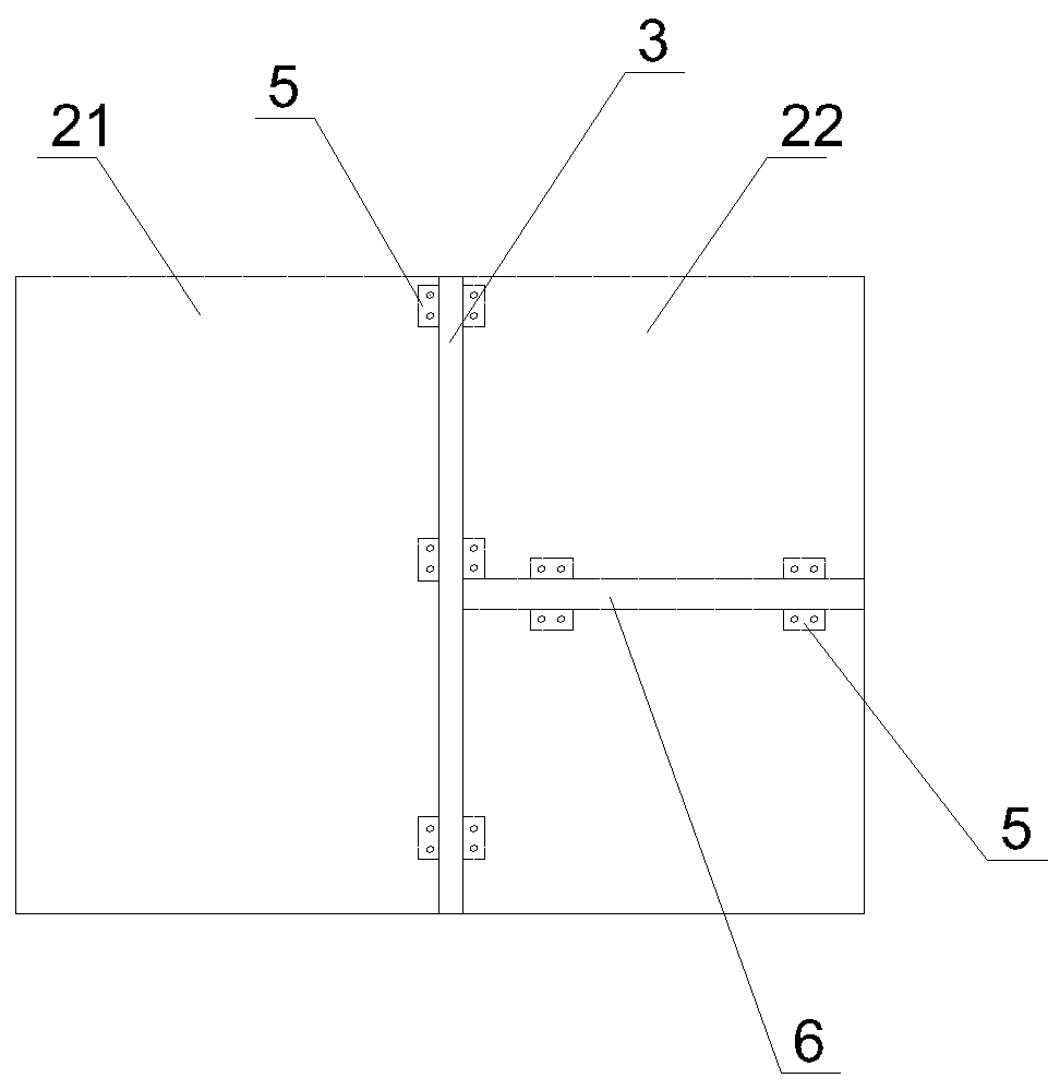
[0018] Embodiment 1: A detachable flood wall with a corrugated floor, which is suitable for waterproof areas of underground passages. see figure 1 and image 3 , on the ground in the passage area, a concrete corrugated surface foundation 1 is preset, and its upper surface is a corrugated surface. Under normal circumstances, simple laying treatment on the surface of the corrugated surface foundation 1 will not affect normal traffic.
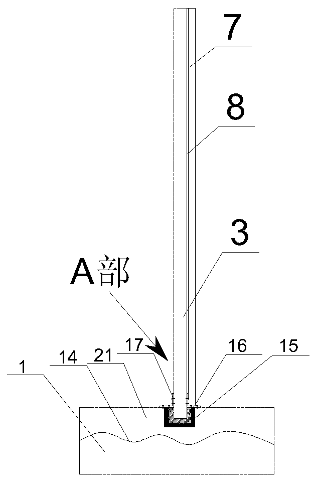
[0019] A corrugated surface base is provided, and its lower surface is a corrugated surface. The upper surface of the concrete corrugated surface foundation 1 and the lower surface of the corrugated surface base can be matched and fastened together. A water retaining plate 3 is vertically fixed on the upper side of the corrugated surface base, and the water retaining plate 3 divides the corrugated surface base into a water-facing section 21 of the corrugated surface and a backwater section 22 of the corrugated surface. Set the backstay 4. When...
Embodiment 2
[0023] Embodiment 2: Another detachable flood wall with a corrugated bottom plate is suitable for a specific flood control area. Its main interior is as embodiment 1, but multiple parallel vertical walls are set to form multiple channels. like Figure 4 As shown, a vertical wall is provided on both sides corresponding to the water retaining plate 3, a wall fixed side 7 is arranged on the vertical wall, and a wall sealing layer 8 is provided between the two ends of the water retaining plate 3 and the wall fixed side 7 . see Figure 6 As shown, the docking fixture 10 includes a clamp body 11 and a clamp slot 12 arranged on one side of the clamp body 11, and compression bolts 13 are respectively installed on the two side walls of the clamp slot 12, and the clamp slot 12 is simultaneously Fastened on the outer side of the adjacent compression flange 31 , the adjacent compression flange 31 is compressed and fixed by the compression bolt 13 .
PUM
 Abstract
Description
Claims
Application Information
 - R&D
- Intellectual Property
- Life Sciences
- Materials
- Tech Scout
- Unparalleled Data Quality
- Higher Quality Content
- 60% Fewer Hallucinations
Browse by: Latest US Patents, China's latest patents, Technical Efficacy Thesaurus, Application Domain, Technology Topic, Popular Technical Reports.
© 2025 PatSnap. All rights reserved.Legal|Privacy policy|Modern Slavery Act Transparency Statement|Sitemap|About US| Contact US: help@patsnap.com


