Automatic rebar binding machine

An automatic technology for steel bar binding, which is applied in the fields of construction, building structure, and building material processing, etc., can solve the problems of high labor intensity and slow construction speed, and achieve a high degree of automation, improve binding efficiency, fast and reliable binding Effect

Pending Publication Date: 2018-01-16
福建谊和天宸科技有限公司
View PDF6 Cites 6 Cited by
  • Summary
  • Abstract
  • Description
  • Claims
  • Application Information

AI Technical Summary

Problems solved by technology

[0002] In the construction industry, steel bars are equivalent to the bones of the human body, which play the role of supporting and tying the building body. A large number of steel bars need to be fixed in sequence according to the

Method used


Image

  • Automatic rebar binding machine
  • Automatic rebar binding machine
  • Automatic rebar binding machine

Examples


Example Embodiment

[0023] The content of the present invention will be described in detail below in conjunction with the drawings and embodiments of the specification:

[0024] Such as Figure 1 to 11 Shown is a schematic diagram of an embodiment of an automatic rebar tying machine provided by the present invention.
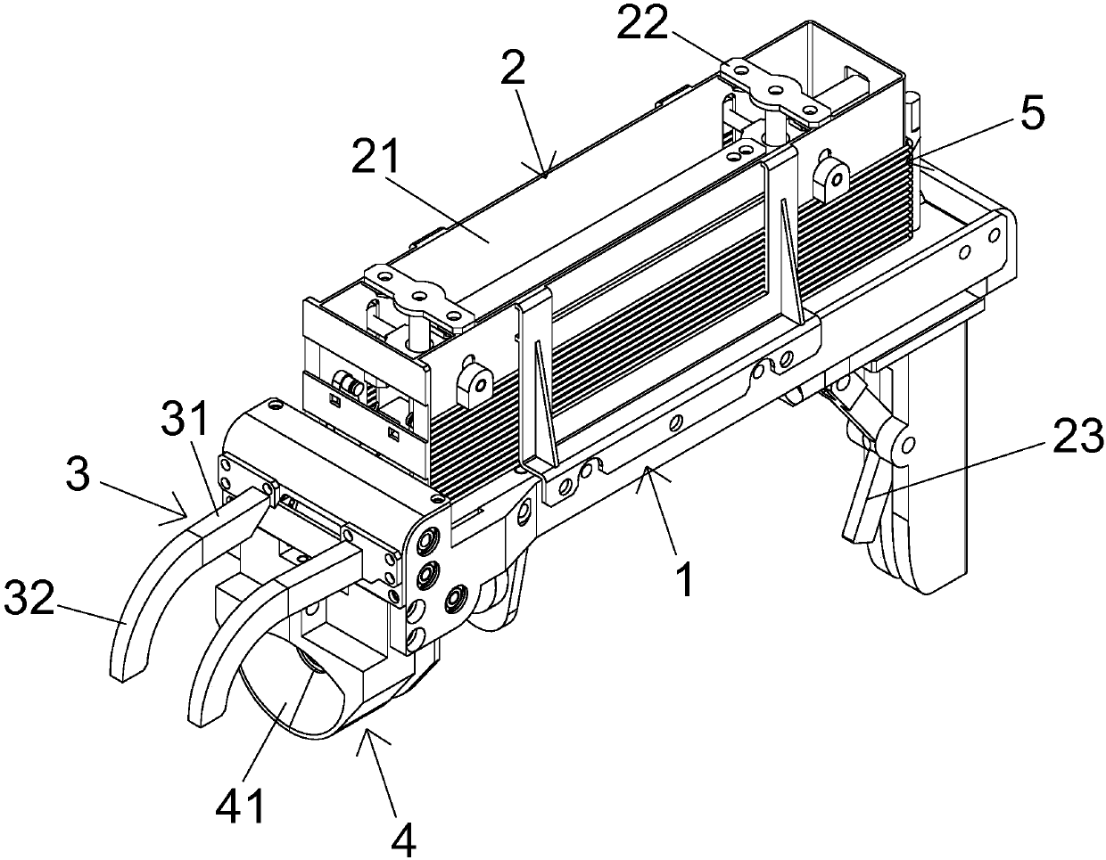
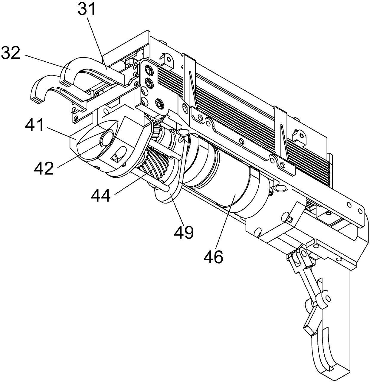
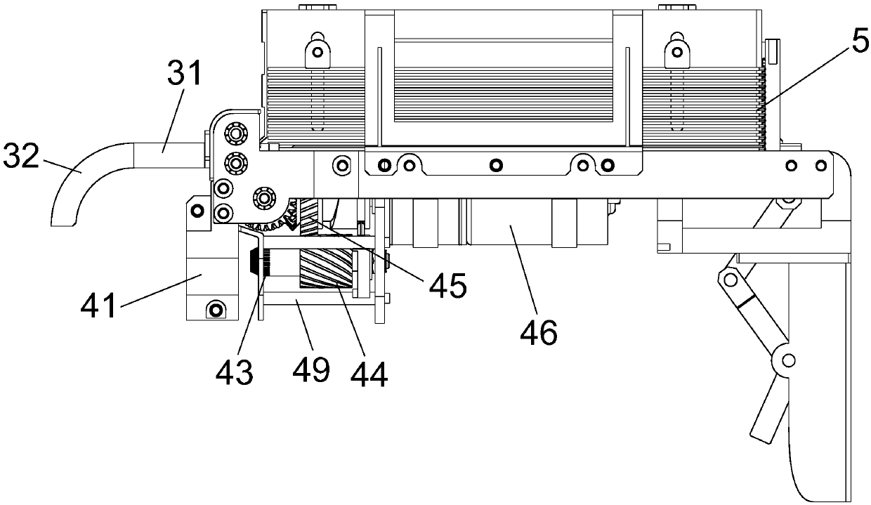
[0025] An automatic rebar tying machine, which includes a body 1, a wire storage mechanism for storing U-shaped wire ties 5, and a wire outlet that is connected to the wire storage mechanism 2 and bent the two free ends of the U-shaped wire ties 5 to one side The mechanism 3 and the binding mechanism 4 correspondingly arranged on the bending side of the U-shaped wire tie 5 and tightening the two free ends of the U-shaped wire tie 5; the wire-out mechanism 3 includes two guide rails 31 arranged at intervals, and the guide rails 31 An arc section 32 bent to one side of the binding mechanism 4 is provided at the exit of

[0026] The invention adopts a buckle tying method, which is used for...


PUM


Abstract

The invention relates to an automatic rebar binding machine. The automatic rebar binding machine comprises a machine body, a wire storage mechanism for storing U-shaped binding wires, a wire discharging mechanism which communicates with the wire storage mechanism and is used for bending the two free ends of each U-shaped binding wire towards one side, and a binding mechanism which is correspondingly arranged on the bent sides of the U-shaped binding wires and used for conducting tightening operation on the two free ends of each U-shaped binding wire. The wire discharging mechanism comprises two guide rails arranged in a spaced mode, and outlets of the guide rails are provided with arc-shaped sections bending towards one side of the binding mechanism. The invention aims to provide the automatic rebar binding machine which is high in automation degree. The automatic rebar binding machine has the advantages that the wire storage mechanism, the wire discharging mechanism and the binding mechanism are arranged, the U-shaped binding wires can be automatically bent, the free ends of the U-shaped binding wires can be automatically tightened, the automation degree is high, and the rebar binding efficiency is greatly improved.

Description

technical field [0001] The invention relates to an automatic steel bar binding machine. Background technique [0002] In the construction industry, steel bars are equivalent to the bones of the human body, which play the role of supporting and tying the building body. A large number of steel bars need to be fixed in sequence according to the engineering drawings before pouring concrete, so that the steel bar skeleton can be fixed reliably. Traditional steel bar binding is still used. Manual operation is not only labor-intensive, but also slow in construction speed. Contents of the invention [0003] The purpose of the present invention is to provide an automatic steel bar binding machine with a high degree of automation. [0004] The purpose of the present invention is achieved through the following technical solutions: an automatic steel bar binding machine, which includes a body, a wire storage mechanism for storing U-shaped wires, and communicates with the wire storage...

Claims


Application Information

Patent Timeline
IPC IPC(8): E04G21/12
Inventor 陈兵
Owner 福建谊和天宸科技有限公司
Why Eureka
Try Eureka