Camera and mobile terminal
A camera and lens technology, applied in the field of communication, can solve the problem of poor telephoto effect of the camera, and achieve the effect of improving the telephoto effect and small field of view.
- Summary
- Abstract
- Description
- Claims
- Application Information
AI Technical Summary
Problems solved by technology
Method used
Image

Examples
no. 1 example
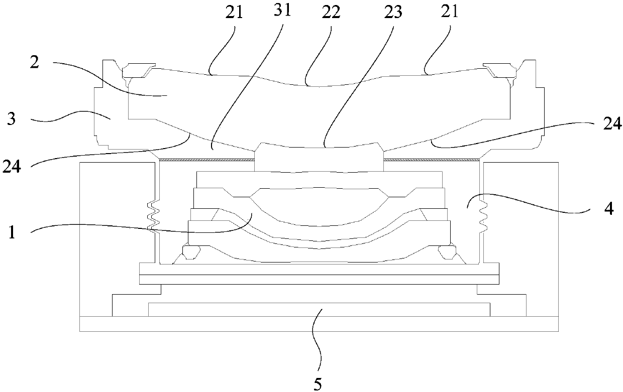
[0038] like Figure 1 to Figure 8 As shown, a camera includes a lens 1 and a light reflection mechanism 2 assembled on the lens 1 .
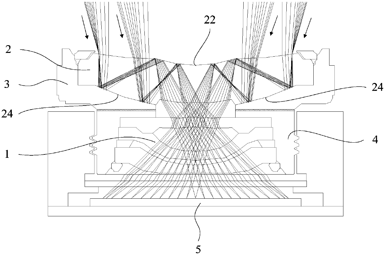
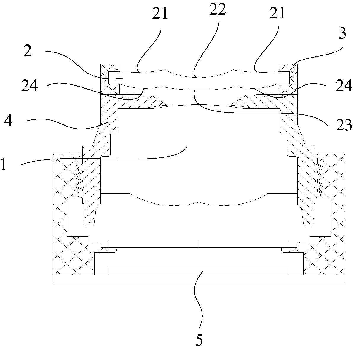
[0039] The light refraction mechanism 2 includes a first side and a second side oppositely arranged; the first side of the light refraction mechanism 2 is provided with a first refraction surface 21 and a first reflection surface 22, and the first reflection surface 22 is arranged on the first side In the middle area, the first refracting surface 21 is set around the first reflecting surface 22 . The second side of the light refraction mechanism 2 is provided with a second refraction surface 23 and a second reflection surface 24, the second refraction surface 23 is provided in the middle area of the second side, and the second reflection surface 24 is provided around the second refraction surface 23; The second refracting surface 23 faces the lens 1 .
[0040] External light enters the light refraction mechanism 2 from the first refraction s...
no. 2 example
[0064] like Figure 9 to Figure 13 As shown, on the basis of the first embodiment, the light reflection mechanism 2 includes a first reflection part 25 and a second reflection part 26, and the first refraction surface 21, the first reflection surface 22 and the second refraction surface 23 are all The second reflection surface 24 is disposed on the second reflection portion 26 and disposed on the first reflection portion 25 .
[0065] The difference between the embodiment of the present invention and the first embodiment is that the light reflection mechanism 2 in the first embodiment adopts an integral structure, while the embodiment of the present invention splits the light reflection mechanism 2 into two reflection parts.
[0066] Due to the adoption of the above-mentioned different technical solutions, the embodiment of the present invention has the following further beneficial effects compared with the first embodiment:
[0067] On the one hand, the integral light refrac...
no. 3 example
[0081] like Figure 14 to Figure 17 As shown, on the basis of the first embodiment or the second embodiment, the camera also includes a first barrel 3 and a second barrel 4; the lens 1 includes N lenses 11, and the light refraction mechanism 2 and N lenses 11 The first M lenses 11 are assembled in the first barrel 3, and the lenses 11 of the N lenses 11 except the first M lenses 11 are assembled in the second barrel 4; the first barrel 3 is fixedly arranged in the second barrel 3. On the barrel 4; N is a positive integer greater than or equal to 2, M is a positive integer greater than or equal to 1, and N is greater than M.
[0082] in, Figure 14 It shows an embodiment in which the lens 1 includes four lenses 11 , the light reflection mechanism 2 and the first lens 11 are assembled together in the first cylinder 3 , and the remaining three lenses 11 are jointly assembled in the second cylinder 4 . Figure 16 It shows an embodiment that the lens 1 includes two lenses 11 , th...
PUM
 Abstract
Description
Claims
Application Information
 - R&D
- Intellectual Property
- Life Sciences
- Materials
- Tech Scout
- Unparalleled Data Quality
- Higher Quality Content
- 60% Fewer Hallucinations
Browse by: Latest US Patents, China's latest patents, Technical Efficacy Thesaurus, Application Domain, Technology Topic, Popular Technical Reports.
© 2025 PatSnap. All rights reserved.Legal|Privacy policy|Modern Slavery Act Transparency Statement|Sitemap|About US| Contact US: help@patsnap.com