Resistance interference prevention method between circuit boards

A resistance interference, circuit board technology, applied in the direction of printed circuit components, printed circuits connected to non-printed electrical components, etc., can solve the problems of reducing anti-interference ability, high frequency of common mode interference, and unsatisfactory effect. , to achieve the effect of improving the anti-drying ability

Inactive Publication Date: 2018-01-16
安徽辉墨教学仪器有限公司
View PDF3 Cites 0 Cited by
  • Summary
  • Abstract
  • Description
  • Claims
  • Application Information

AI Technical Summary

Problems solved by technology

For this reason, in conventional devices, measures such as isolation and filtering have been taken, which have produced certain positive effects, but the effects are not very satisfactory. Studies have shown that the source of interference is mainly the surge (analog quantity) introduced from the outside through the terminals of the device. input, digital input, output, DC power supply l

Method used


Image

  • Resistance interference prevention method between circuit boards

Examples


Example Embodiment

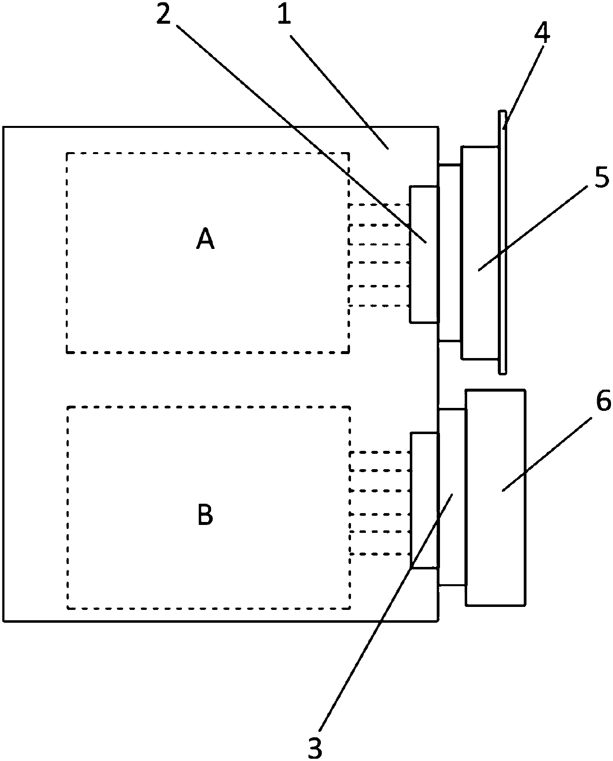
[0017] like figure 1 As shown, a method for resisting resistance interference between circuit boards includes the following steps:

[0018] S1: provide a circuit board plug-in 1, and the circuit board plug-in 1 is respectively provided with a first circuit board A and a second circuit board B;

[0019] S2: a first plug 2 and a second plug 3 are respectively provided on the circuit board plug-in 1, a first shielding cover is provided between the first plug 2 and the first circuit board A, and the second plug 3 and the second circuit board B are provided A second shield is arranged between;

[0020] S3: Connect all input and output lines of the first circuit board A to the first plug 2 through the first shield, and connect all the input and output lines of the second circuit board B to the second plug through the second shield. 3.

[0021] like figure 1 As shown, the first plug is also connected with a socket 5, and the socket 5 is connected with a backplane 4, and the inter...


PUM


Abstract

The invention provides a resistance interference prevention method between circuit boards. The method comprises the following steps of S1, providing a circuit board card and respectively arranging thefirst circuit board and the second circuit board on the circuit board card, S2, respectively arranging a first plug and a second plug on the circuit board card, arranging a first shield cover betweenthe first plug and the first circuit board, and arranging a second shield cover between the second plug and the second circuit board, and S3, internally connecting all input and output lines of the first circuit board with the first plug by the first shield cover, and internally connecting all input and output lines of the second circuit board with the second plug by the second shield cover. Themethod improves the interference prevention capacity between the circuit boards.

Description

technical field [0001] The invention belongs to the technical field of circuit boards, and in particular relates to an anti-resistance interference method between circuit boards. Background technique [0002] At present, in various microcomputer control devices, especially in microcomputer relay protection devices, it is a relatively common problem that strong electric signals are serially inserted into weak electric circuits to interfere with the normal operation of the devices. For this reason, in conventional devices, measures such as isolation and filtering have been adopted, which have produced certain positive effects, but the effects are not very satisfactory. Research has shown that the source of interference is mainly the surge (analog quantity) introduced from the outside through the device terminals. input, digital input, output, DC power input, etc.). In the existing device, the strong current, weak current terminals and loops are mixed on the chassis structure ...

Claims


Application Information

Patent Timeline
IPC IPC(8): H05K1/02H05K1/18
Inventor 唐寿高张高伦
Owner 安徽辉墨教学仪器有限公司
Why Eureka
Try Eureka