
Directional automatic control bending machine

An automatic control and bending machine technology, applied in the field of bending machines, can solve the problems of different bending angles of steel bars, and the bending angle is not easy to control.

Inactive Publication Date: 2018-01-19
中山市睿丰智能科技有限公司
View PDF1 Cites 4 Cited by
  • Summary
  • Abstract
  • Description
  • Claims
  • Application Information

AI Technical Summary

Problems solved by technology

[0004] Aiming at the deficiencies of the existing technology, the purpose of the present invention is to provide a directional automatic control bending machine to solve the problem in the prior art that the bending angle is not easy to control due to manual operation during bending, resulting in different bending angles of steel bars

Method used


Image

  • Directional automatic control bending machine
  • Directional automatic control bending machine
  • Directional automatic control bending machine

Examples


Embodiment Construction

[0019] In order to make the technical means, creative features, goals and effects achieved by the present invention easy to understand, the present invention will be further described below in conjunction with specific embodiments.

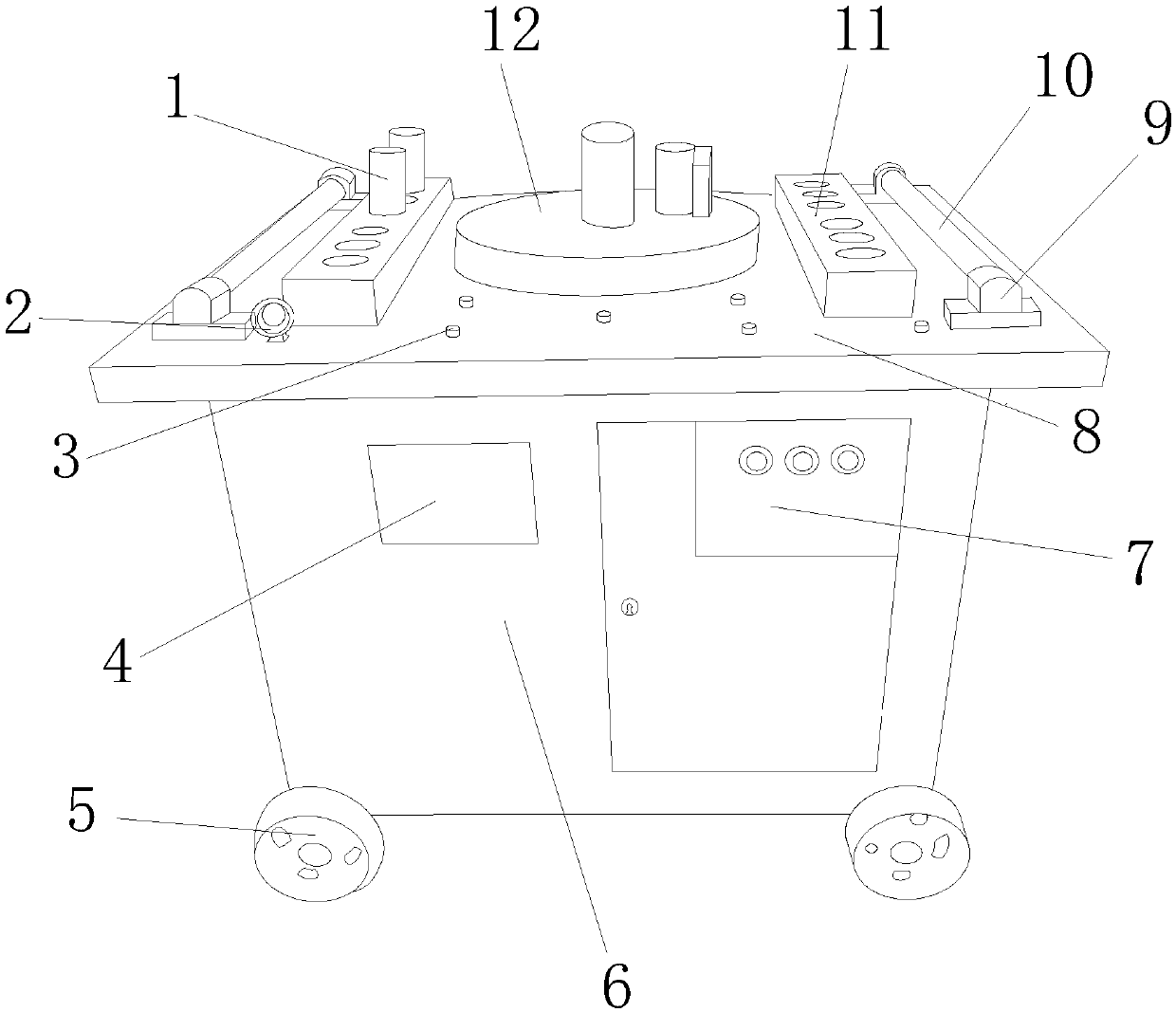
[0020] see figure 1 , figure 2 , the present invention provides a technical solution for a directional automatic control bending machine: its structure includes a movable clamping column 1, a fixed ring 2, a bolt 3, a pasting plate 4, wheels 5, a support box 6, a control board 7, an alloy plate 8, a fixed Sleeve 9, support shaft 10, insertion seat 11, automatic orientation bending disc 12, the movable clamp column 1 is nested with the insertion seat 11, the bottom of the fixed ring 2 is welded with the alloy plate 8, and the bolt 3 It is screwed with the alloy plate 8, the paste plate 4 is attached to the front surface of the support box 6, the wheels 5 are connected to the support box 6, the control board 7 is attached to the support box 6, an...


PUM

PropertyMeasurementUnit
diameteraaaaaaaaaa

Abstract

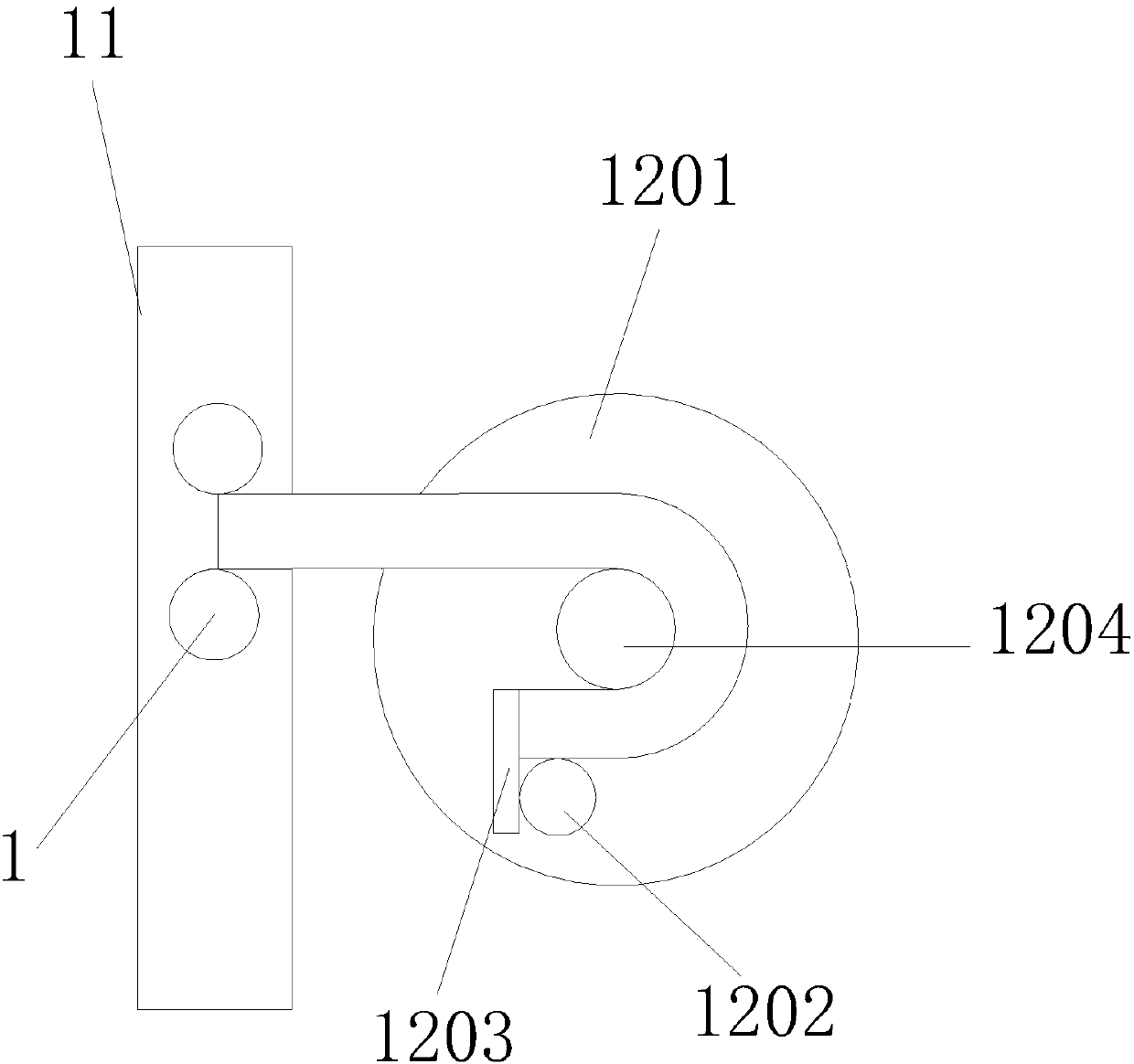
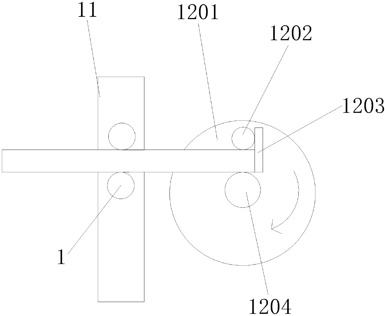
The invention discloses a directional automatic control bending machine which structurally comprises movable clamping columns, a fixing ring, bolts, a sticking plate, wheels, a supporting box, a control plate, an alloy plate, a fixing sleeve, a supporting shaft, an inserting seat and an automatic directional bending disc. The movable clamping columns are embedded in the inserting seat, and the bottom of the fixing ring is welded to the alloy plate; and the bolts are in threaded connection with the alloy plate. The directional automatic control bending machine is structurally provided with theautomatic directional bending disc, when the directional automatic control bending machine works, steel bars penetrates through the two movable clamping columns, the fixing effect is achieved, and thesteel bars stretch into the movable clamping columns till the steel bars abut against stopping bodies; at this moment, a rotary disc starts to rotate clockwise, a center shaft is fixed to the rotarydisc, and a bearing rotates along with the rotary disc and drives one ends of the steel bars to be bent till the steel bars are bent to form the needed angles; and thus, the stretched steel bars can be directionally bent so that the steel bar bending degrees can be consistent, and the working efficiency is improved.

Description

technical field [0001] The invention relates to a directional automatic control bending machine, which belongs to the technical field of bending machines. Background technique [0002] In many projects, the bending of steel bars is the basic work content. When processing steel bars of φ6-φ40mm, one end of the steel bars needs to be bent into different semicircular models. Currently, the existing bending machines on the market are manually braked. It is easy to make mistakes, the bending angle of the steel bar is not easy to grasp, and it is time-consuming and laborious, the work efficiency is low, and the qualified rate is low simultaneously. [0003] The prior art discloses a directional automatic control bending machine with application number 201520629848.0, which includes: a frame on which a table panel is arranged; On the table panel, the center of the working disc is provided with a circular center sleeve, the center sleeve is provided with a center sleeve shaft, and ...

Claims


Application Information

Patent Timeline
Patent Type & Authority Applications(China)
IPC IPC(8): B21F1/00
Inventor 朱燕雅
Owner 中山市睿丰智能科技有限公司
Learn More