Milling cutter with spiral chip separating trough

A technology of chip splitting groove and spiral groove, which is applied in the direction of milling cutter, milling machine equipment, manufacturing tools, etc., can solve the problems of secondary pollution in the working environment, flying debris, and burns on workers' skin, achieving less secondary pollution and better structure Simple, easy-to-use effects

Inactive Publication Date: 2018-01-19
CHANGZHOU MAITENG TOOLS CO LTD
View PDF0 Cites 2 Cited by
  • Summary
  • Abstract
  • Description
  • Claims
  • Application Information

AI Technical Summary

Problems solved by technology

[0003] However, the existing milling cutters still have certain defects when they are used. When the existing milling cutters are milling planes, chips often fly everywhere, which not only causes secondary pollution to the working environment, but also causes high temperature in the chips. Worker's skin burns

Method used


Image

  • Milling cutter with spiral chip separating trough
  • Milling cutter with spiral chip separating trough
  • Milling cutter with spiral chip separating trough

Examples


Embodiment Construction

[0017] The technical solutions in the embodiments of the present invention will be clearly and completely described below in conjunction with the accompanying drawings in the embodiments of the present invention. Obviously, the described embodiments are only a part of the embodiments of the present invention, rather than all the embodiments. Based on the embodiments of the present invention, all other embodiments obtained by those of ordinary skill in the art without creative work shall fall within the protection scope of the present invention.

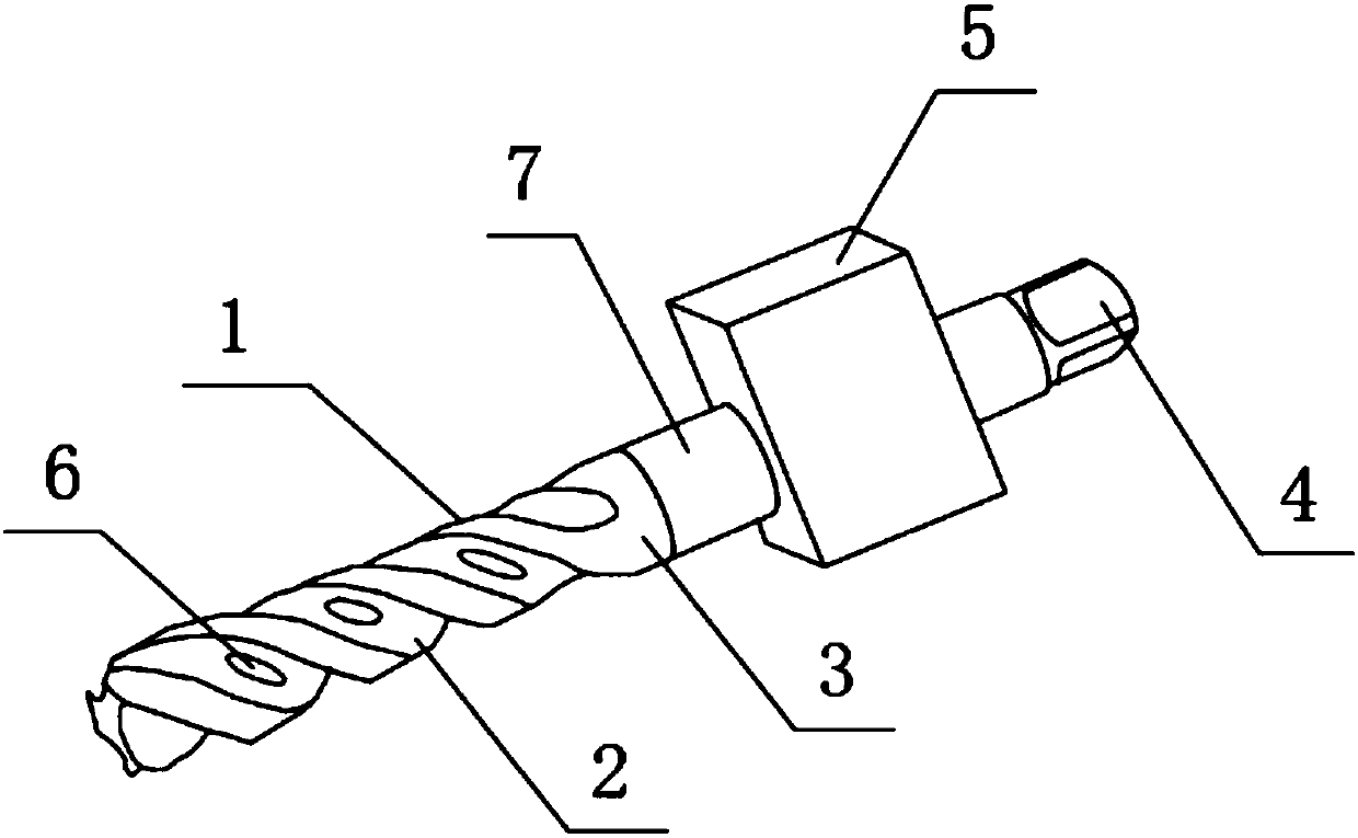
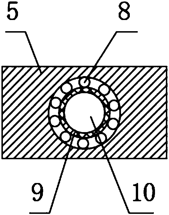
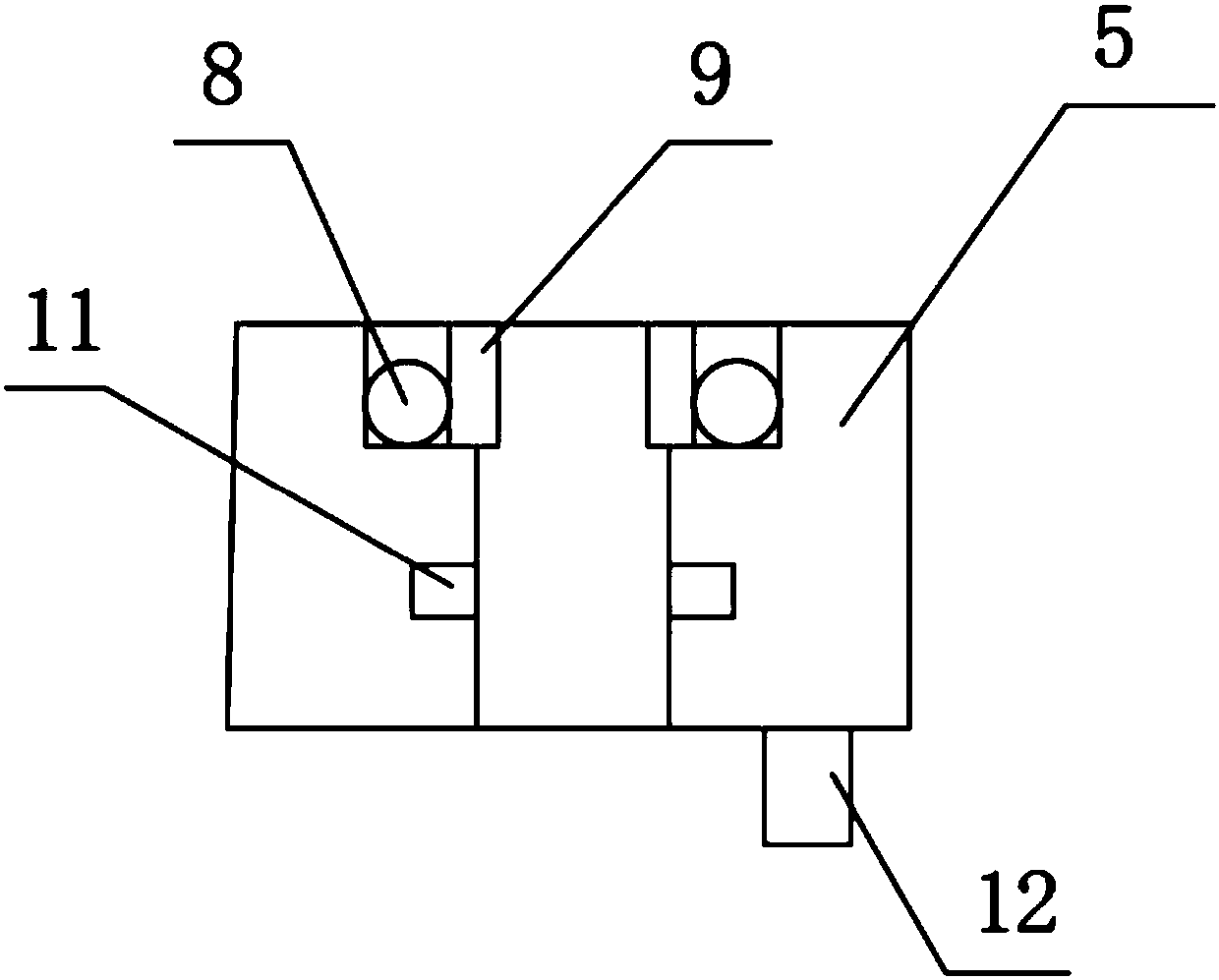
[0018] See Figure 1-4 As shown, a milling cutter with a spiral chip flute includes a working head 3, a spiral groove 2 is arranged inside the working head 3, a first inlet 6 is arranged inside the spiral groove 2, and a first cutting is arranged on one side of the spiral groove 2. Edge 1, the bottom of the working head 3 is provided with a second cutting edge 13, a second inlet 14 is provided on one side of the second cutting edge 13, a...


PUM


Abstract

The invention discloses a milling cutter with a spiral chip separating trough. The milling cutter comprises a first cutting blade, a spiral trough, a working head, a connecting head, an air suction box, a first feeding port, a connecting rod, a ball, an inner ring, a plug hole, a first discharging port, a second discharging port, a second cutting blade and a second feeding port. The milling cutterhas the beneficial effects that chips generated when hole milling is conducted by using the milling cutter can be sucked into the milling cutter by arranging the first feeding port in the spiral trough, therefore the chips are prevented from being detained in a hole, chips generated when plane cutting is conducted by utilizing the second cutting blade can be sucked into the milling cutter throughthe second feeding port, the chips sucked into the milling cutter enter the air suction box through the first discharging port, and then are exhausted out of the air suction box through the second discharging port, the chips can be directionally exhausted through the second discharging port, and thus occurrence of the phenomenon that the chips fly around can be prevented The milling cutter has the characteristics of being simple in structure, less in secondary pollution, convenient to use and the like.

Description

Technical field [0001] The invention relates to a milling cutter, in particular to a milling cutter with a spiral chip groove, belonging to the field of mechanical processing applications. Background technique [0002] A milling cutter is a rotary tool with one or more teeth used for milling. When working, each cutter tooth intermittently cuts off the margin of the workpiece. Milling cutters are mainly used for machining planes, steps, grooves, forming surfaces and cutting workpieces on milling machines. [0003] However, the existing milling cutter still has certain defects when it is used. When the existing milling cutter is milling the plane, it often causes the debris to fly everywhere, which not only causes secondary pollution to the working environment, but also causes the high temperature of the debris. Workers burned their skin. Summary of the invention [0004] The purpose of the present invention is to provide a milling cutter with spiral chip flutes in order to solve t...

Claims


Application Information

Patent Timeline
Patent Type & Authority Applications(China)
IPC IPC(8): B23C5/02
Inventor 蒋勋
Owner CHANGZHOU MAITENG TOOLS CO LTD
Why Eureka
Try Eureka