Automatic sponge filling device

A sponge, automatic technology, applied in printing and other directions, can solve the problems of heavy workload, sponge roll angle, high purchase cost, and achieve the effect of improving filling efficiency, good product quality, and reducing costs

Inactive Publication Date: 2018-01-19
北海市天硌打印耗材有限公司
0 Cites 0 Cited by

AI-Extracted Technical Summary

Problems solved by technology

When assembling the sponge, the operator needs to put the sponge and the ink cartridge into the open and close compression tooling and the cotton filling port by hand, which may cause the risk of crushing the hands and the product, so there is a great safety hazard in the operation
Moreover, the angle, speed, and depth of manually inserting the sponge cavity of the ink cartridge into the cotton opening cannot be consistent every time, and it is easy f...

Method used

[0057] Two first casters 310, which are respectively arranged at the bottom of the horizontal portion of the first block 163, the two first casters 310 are respectively in contact with the top of the ba...

Abstract

The invention discloses an automatic sponge filling device. The automatic sponge filling device comprises a base, a first push block, a first power device, a second push block, a second power device,two first clamping blocks, two first foot wheels, two first fixing blocks, two first guide rods, two first springs and two first sponge press blocks. A first partition, a second partition and a thirdpartition are arranged on the base. The first push block is arranged in a first groove. The first power device is connected with the first push block. The second push block is arranged in a second groove. The second power device is connected with the second push block. The two first clamping blocks both are arranged on the base. The two first foot wheels are correspondingly arranged at the bottomsof the horizontal portions of first block bodies. The two first fixing blocks are correspondingly located on the outer sides of the first clamping blocks. Each first guide rod is arranged between thecorresponding first clamping block and the first fixing block opposite to the first clamping block. Each first spring is arranged in the corresponding first guide rod. The two first sponge press blocks are correspondingly opposite to a first region and a second region. By the adoption of the automatic sponge filling device, filling of three pieces of sponge can be completed at a time, the fillingefficiency is improved greatly, and meanwhile the safety and the quality of products are improved.

Application Domain

Technology Topic

EngineeringFill device

Image

  • Automatic sponge filling device
  • Automatic sponge filling device
  • Automatic sponge filling device

Examples

  • Experimental program(1)

Example Embodiment

[0048] The present invention will be further described in detail below with reference to the accompanying drawings, so that those skilled in the art can implement it with reference to the text of the description.
[0049] It should be noted that in the description of the present invention, the terms "horizontal", "vertical", "upper", "lower", "front", "rear", "left", "right", "vertical", The orientation or positional relationship indicated by "horizontal", "top", "bottom", "inner", "outer", etc. is based on the orientation or positional relationship shown in the drawings, and is only for the convenience of describing the present invention and simplifying the description, and It does not indicate or imply that the pointed device or element must have a specific orientation, be constructed and operated in a specific orientation, and therefore cannot be understood as a limitation of the present invention.
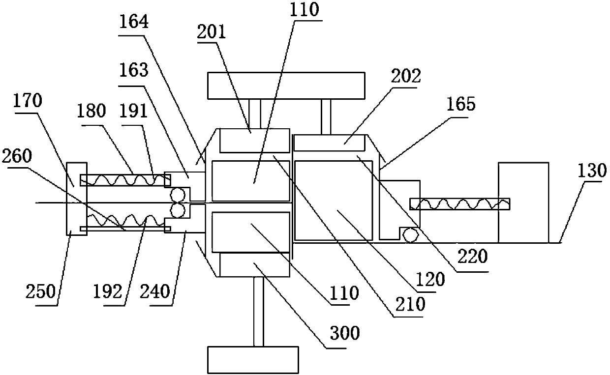
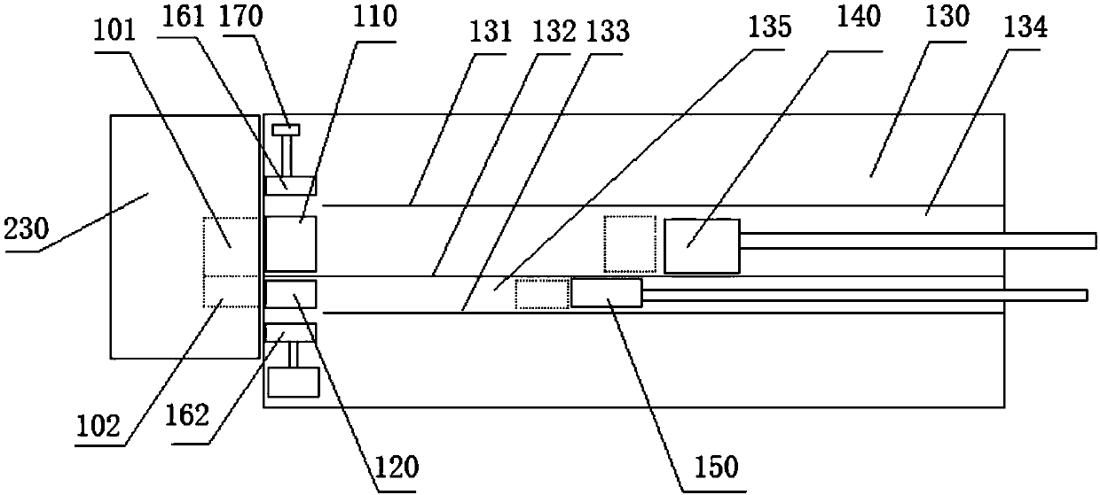
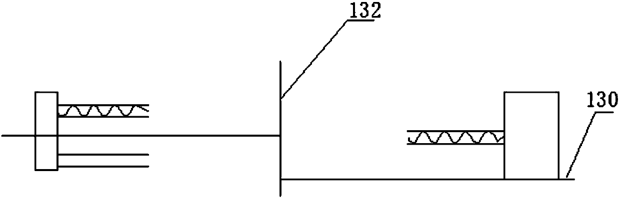
[0050] Such as Figure 1 to Figure 9 As shown, the present invention provides a device for automatically filling sponges, which is used to fill two sponge cavities of different sizes on the ink cartridge 100. Among them, two sponges of the same size in the ink cartridge 100 (referred to as the first sponge 110) They are respectively arranged horizontally in the first sponge cavity 101, and a sponge of another size (the second sponge 120 for short) is arranged vertically in the second sponge cavity 102. The first sponge 110 and the second sponge 120 are both rectangular parallelepiped and automatically filled. The sponge-mounted devices include:
[0051] The base 130, which is in the transverse direction (referring to figure 2 In the left and right directions or figure 1 In the front-rear direction), and the top of the base 130 is longitudinally (referring to figure 2 In the front-to-back direction or figure 1 The first partition 131, the second partition 132, and the third partition 133 are sequentially spaced in the left-right direction), that is, the second partition 132 is provided between the first partition 131 and the third partition 133, The first partition 131, the second partition 132, and the third partition 133 are parallel to each other, and all extend in the transverse direction, and are respectively perpendicular to the base 130. The first partition 131, the second partition 132 and the third partition The partitions 133 are respectively fixedly connected to the base 130, the length of the second partition 132 is equal to the length of the base 130 in the transverse direction, and the first partition 131 and the third partition 133 are along the transverse direction. One end of the direction ( figure 2 The right ends of the first partition 131 and the third partition 133) and one end of the base 130 in the transverse direction ( figure 2 The right end of the middle base 130) is flush, and the length of both is smaller than the length of the base 130 in the transverse direction, that is, the other end of the first partition 131 and the third partition 133 in the transverse direction ( figure 2 The left ends of the first partition 131 and the third partition 133) and the other end ( figure 2 The left end of the middle base 130 is not flush, so that the first partition 131 and the third partition 133 cannot prevent the movement of the two first clamping blocks in the longitudinal direction, and the top of the base 130 is covered by the second partition 132 is divided into two square areas, that is, the areas on both sides of the second partition 132 on the base 130 are squares, and the two square areas have the same length and are aligned at both ends. The base 130, The first partition 131 and the second partition 132 enclose a first groove 134, and the base 130, the third partition 133 and the second partition 132 enclose a second groove 135; The bottom of the first groove 134 can be flush with the bottom of the second groove 135, and can also be higher or lower than the bottom of the second groove 135.
[0052] The first push block 140 is arranged in the first groove 134, that is, the longitudinal width of the first push block 140 is smaller than the width of the first groove 134;
[0053] A first power device, which is connected to the first push block 140, and is used to drive the first push block 140 to reciprocate in a transverse direction;
[0054] The second pushing block 150 is arranged in the second groove 135;
[0055] The second power device, which is connected to the second push block 150, is used to drive the second push block 150 to reciprocate in the transverse direction, that is, the longitudinal width of the second push block 150 is smaller than the width of the second groove 135;
[0056] Two first clamping blocks, which are figure 1 The first clamping block on the left side (referred to as the first clamping block A161) and the first clamping block on the right side (referred to as the first clamping block B162), the first clamping block A161 and the first clamping block B162 are both arranged on the base 130, and are respectively located between the other end of the first partition 131 in the transverse direction and the other end of the base 130 in the transverse direction (that is, the first clamping block A161 is not opposite to the first partition 131) , And between the other end of the third partition 133 in the transverse direction and the other end of the base 130 in the transverse direction (that is, the first clamp block B162 is not opposite to the third partition 133), the first clamp The block A161 and the first clamping block B162 both include a first block 163 and a first plate that are integrally formed. The first block 163 is inverted L-shaped, and its bottom is in contact with or attached to the base 130. The first block The vertical part and the horizontal part of the body 163 are both rectangular parallelepiped. The vertical part of the first block 163 is parallel to the second partition 132, and the free end of the horizontal part is away from the second partition 132. The first plate is Square, and parallel to the second partition 132, the first plate is fixed on the vertical part of the first block 163 (ie figure 1 The right side of the first clamping block A161 and the left side of the first clamping block B162), and the bottom of the first plate is in contact with the base 130, and the top is higher than the top of the first block 163, That is, the first plate (first plate C164) on the first clamping block A161 is fixed on the right side of the first clamping block A161, and the first plate (first plate D165) on the first clamping block B162 ) Is fixedly installed on the left side of the first clamping block B162, one side of the first plate in the transverse direction and one side of the first block 163 in the transverse direction are respectively aligned with the upper side of the base 130 The other side in the transverse direction is flush (e.g. figure 2 As shown, that is, the left side of the first board and the left side of the first block 163 are flush with the left side of the base 130 respectively), the vertical length of one first board is smaller than that of the other first board Straight length; the first plate with the smaller vertical length ( figure 1 The first plate on the left in the middle, referred to as the first plate C164) is used to compress the first sponge 110 from the side, and the first plate with a larger vertical length ( figure 1 The first plate on the right side (referred to as the first plate D165) is used to compress the second sponge 120 from the side.
[0057] Two first casters 310, which are respectively arranged at the bottom of the horizontal portion of the first block 163, and the two first casters 310 respectively contact the top of the base 130 and are not opposite to the first plate ; The first caster 310 can reduce the friction between the first clamping block and the base 130 during the movement.
[0058] Two first fixed blocks 170, such as figure 1 As shown, they are respectively fixed on the other end of the base 130 along the transverse direction, and are respectively located outside the two first clamping blocks, and are respectively opposite to the two first clamping blocks;
[0059] Two first guide rods 180, a first guide rod 180 is respectively arranged between each first clamping block and the first fixed block 170 opposite to it. The first guide rod 180 is cylindrical in shape and arranged along the longitudinal direction , The first clamping block and the outer first fixing block 170 are respectively provided with a cylindrical first blind hole, the first blind hole on the first clamping block and the first fixing block 170 on the outer side The blind holes are opposed to each other so that the two ends of a connecting rod are inserted into the two opposite first blind holes respectively. The diameter of the first blind hole is equal to the outer diameter of the first guide rod 180. Both ends of the guide rod 180 are respectively inserted into the two first blind holes; in this way, the first clamping block A161 and the first clamping block B162 can only move in the longitudinal direction. The depth of the first blind hole needs to be deep enough so that when the first clamping block A161 and the first clamping block B162 move, both ends of the first guide rod 180 are always inserted into the two corresponding first blind holes.
[0060] Two first springs, which are figure 1 The first spring on the left side (referred to as the first spring E191) and the first spring on the right side (referred to as the first spring F192), each first guide rod 180 is provided with a first spring, two of the first spring The ends are respectively located in the two first blind holes, and are respectively fixedly connected to the corresponding first fixing block 170 and the first clamping block in the first blind holes, the first spring extends or contracts in the longitudinal direction; the first spring It is stretched after being pressed down by the first cotton press block, and returns to its natural state after the first cotton press block rises.
[0061] Two first pressed cotton blocks, which are figure 1 The first cotton press block on the left side (referred to as the first cotton press block G201) and the first cotton press block on the right (referred to as the first cotton press block H202), the first cotton press block G201 and the first cotton press H202 Are respectively disposed above the base 130, and are respectively connected to the first area between the other end of the second partition 132 in the transverse direction and a first clamping block, and the upper edge of the second partition 132 The other end in the transverse direction is opposite to the second area between the other first clamping block. The first cotton pressing block G201 and the first cotton pressing block H202 are both composed of an integrally formed second block and a second plate. The second block is in the shape of a rectangular parallelepiped and is arranged in a horizontal direction and is perpendicular to the second partition 132. One end of the second plate is horizontal and connected with an outer side wall of the second block, and the other end is gradually Tilt downward and away from the second block. When the two first springs are in a natural state, the two first plates are located below the other ends of the two second plates. When the When the first cotton press block is opposed to the second partition 132, the first cotton press block is attached to the second partition 132, and the width of one end of the second plate body is The thickness of the first plate is equal, and the base 130, the two first clamping blocks, the two first cotton pressing blocks and the second partition 132 respectively enclose two receiving areas for sponges of two sizes; That is, the first receiving area 210 of the first sponge 110 is enclosed by the base 130, the first clamping block A161, the first cotton pressing block G201, and the second partition 132, and the base 130, the first The clamping block B162, the first cotton pressing block H202 and the second partition 132 enclose the second containing area 220 of the second sponge 120; the power device drives the first cotton pressing block to move up and down.
[0062] Wherein, when the tops of the two first plates are respectively against the bottom of one end of the corresponding second plate (at this time, the first plate is attached to the second block opposite to it, the second pressing block 300 is attached to the second partition 132, the first containing area 210 and the second containing area 220 are both rectangular parallelepiped, the first plate body cannot move longitudinally, the first sponge 110 and the second sponge 120 are compressed to the required size ), the first push block 140 and the second push block 150 can respectively pass through their corresponding containing areas; that is, the sizes of the first push block 140 and the second push block 150 are respectively smaller than or equal to the first push block at this time The size of the receiving area 210 and the second receiving area 220.
[0063] The distance between the other end of the first partition 131 and the third partition 133 in the transverse direction and the other end of the base 130 in the transverse direction is smaller than that of the first push block 140 and the second push block 150, respectively The length along the transverse direction. In this way, the first pushing block 140 and the second pushing block 150 can respectively push the first sponge 110 and the second sponge 120 in the first groove 134 and the second groove 135 to the first receiving area 210 and the second receiving area, respectively In 220, the first groove 134 and the second groove 135 always play a guiding role.
[0064] The device for automatically filling sponges provided by this solution can respectively fill a first sponge 110 and a second sponge 120 into a first sponge cavity 101 and a second sponge cavity 102, or at the same time. The first sponge 110 and the second sponge 120 are filled into the first sponge cavity 101 and the second sponge cavity 102.
[0065] The specific method of filling a first sponge 110 into a first sponge cavity 101 is: adjusting the size of the first containing area 210 to be larger than the size of the first sponge 110, and placing a first sponge 110 in the first groove In 134, the first power device pushes the first push block 140 to push a first sponge 110 from one end of the base 130 in the transverse direction to the first receiving area 210. At this time, the size of the first receiving area 210 is larger than that of the first sponge 110. The size of the sponge 110 is large, the first spring E191 is in a natural state, the distance between the first plate C164 and the second partition 132 is greater than the length of the first sponge 110 in the longitudinal direction, and the second on the first cotton press block G201 The distance between the bottom of the block and the base 130 is greater than the vertical length of the first sponge 110, and then the first cotton pressing block G201 presses down the first sponge 110, while the second plate on the first cotton pressing block G201 faces downwards Press the first plate body C164, the first plate body C164 will move toward the second block on the first cotton pressing block G201 and close to the second block. At this time, the first receiving area 210 is square, the first The circumference of the sponge 110 is compressed, and then a first sponge cavity 101 on the ink cartridge 100 is opposed to the compressed first sponge 110 (the size of the compressed first sponge 110 is smaller than that of the first sponge cavity 101). A power device pushes the first pushing block 140 through the first containing area 210 to push the compressed first sponge 110 into the first sponge cavity 101, and then the first sponge 110 is expanded and fixed in the first sponge cavity 101 in.
[0066] The specific method of filling another first sponge 110 into another first sponge cavity 101 is roughly the same as the specific method of filling one first sponge 110 into one first sponge cavity 101, except that another first sponge 110 After being compressed in the first accommodating area 210, the other first sponge cavity 101 on the ink cartridge 100 is opposed to the other compressed first sponge 110 (the size of the compressed second sponge 110 is larger than that of the other The size of the first sponge cavity 101), the first power device pushes the first push block 140 through the first containing area 210, and can push another first sponge 110 after compression into another first sponge cavity 101, Then another first sponge 110 is expanded and fixed in another first sponge cavity 101.
[0067] The specific method of filling the second sponge 120 into the second sponge cavity 102 is: adjusting the size of the second receiving area 220 to be larger than the size of the second sponge 120, placing the second sponge 120 in the second groove 135, The second power device pushes the second push block 150 to push the second sponge 120 from one end of the base 130 in the transverse direction to the second receiving area 220. At this time, the size of the second receiving area 220 is larger than that of the second sponge 120 , The second spring F is in a natural state, the distance between the first plate D165 and the second partition 132 is greater than the length of the second sponge 120 in the longitudinal direction, and the bottom of the second block on the first cotton press block H202 is The distance between the bases 130 is greater than the vertical length of the second sponge 120, and then the first cotton pressing block H202 presses down the second sponge 120, while the second plate on the first cotton pressing block H202 presses the first plate down D165, the first plate D165 will move toward the second block on the first cotton press block H202 and close to the second block. At this time, the second receiving area 220 is square, and the second sponge 120 is surrounded by After compression, the second sponge cavity 102 on the ink cartridge 100 is opposed to the compressed second sponge 120 (the size of the compressed second sponge 120 is smaller than that of the second sponge cavity 102), and the second power device pushes the second sponge 120 The pushing block 150 passes through the second receiving area 220 to push the compressed second sponge 120 into the second sponge cavity 102, and then the second sponge 120 is expanded and fixed in the second sponge cavity 102.
[0068] The specific method for making the first sponge cavity 101 on the ink cartridge 100 face the compressed first sponge 110 is: embedding the ink cartridge 100 on the ink cartridge 100 mounting seat 230 so that the first sponge cavity 101 and the second sponge cavity 102 With the opening facing outward, a movement device is provided on the ink cartridge 100 mounting seat 230. The movement device is a common XYZ three-axis linkage device. The movement of the movement device can make the first sponge cavity 101 on the ink cartridge 100 and the compressed first The sponge 110 is opposite. Similarly, the second sponge cavity 102 on the ink cartridge 100 can be opposite to the second sponge 120 after compression.
[0069] When the second sponge cavity 102 is filled with sponge, it can be filled alone or together with one of the first sponge cavities 101. At this time, the bottom of the first groove 134 is higher than the bottom of the second groove 135.
[0070] In another technical solution, in the device for automatically filling sponges, when the tops of the two first plates are respectively against the bottom of one end of the corresponding second plate, and the first push block When the 140 and the second push block 150 are located in their corresponding accommodating areas, the first push block 140 and the second push block 150 respectively seal the respective accommodating areas. That is, the lengths of the first push block 140 and the second push block 150 in the longitudinal direction and the vertical direction are respectively the same as the lengths of the first receiving area 210 and the second receiving area 220 in the longitudinal direction and the vertical direction at this time. The lengths of the first push block 140 and the second push block 150 in the transverse direction are respectively greater than or equal to the lengths of the first receiving area 210 and the second receiving area 220 in the transverse direction. In this way, the first pushing block 140 and the second pushing block 150 can respectively pass through the first containing area 210 and the second containing area 220, and can push the first sponge 110 and the second sponge 120 out of the corresponding first containing area. 210 and the second receiving area 220.
[0071] In another technical solution, in the device for automatically filling sponges, the first plate body and the first block 163 connected to it have the same length in the transverse direction, and the first plate body has the same length in the transverse direction. The two side edges spaced apart in the transverse direction are on the plane of the two side surfaces spaced in the transverse direction on the first block 163, so that the other end of the first partition 131 or the third partition 133 in the transverse direction The distance from the other end of the base 130 in the transverse direction is the smallest, which is the length of the first plate in the transverse direction, so that the first sponge 110 and the second sponge 120 can smoothly pass from the first groove 134 and the The two grooves 135 are pushed into the first receiving area 210 and the second receiving area 220.
[0072] In another technical solution, in the device for automatically filling sponges, such as figure 1 As shown, the vertical height of the bottom of the second groove 135 is lower than the vertical height of the bottom of the first groove 134. At this time, the second sponge cavity 102 can be filled together with the first sponge cavity 101 located above. The first sponge 110 is compressed in the first accommodating area 210, while the second sponge 120 is compressed in the second accommodating area 220, and then the first sponge 110 and the second sponge 120 are respectively connected to the first sponge 110 accommodating cavity and the second sponge 120 The sponge 120 accommodating cavities are opposite, the first pushing block 140 and the second pushing block 150 simultaneously push the first sponge 110 and the second sponge 120 into the first sponge cavity 101 and the second sponge cavity 102, and then the other first sponge The sponge 110 is filled into another first sponge cavity 101 to complete the filling of the three sponges.
[0073] In another technical solution, in the device for automatically filling sponges, the bottoms of the two second blocks are flush, and a vertical connecting rod is fixed at the tops, and the tops of the two connecting rods are respectively It is fixedly connected with a horizontally arranged horizontal plate, the horizontal plate is connected with a third power device, and the third power device is used to simultaneously drive the two second blocks (first cotton press blocks) to move up and down. Since the tops of the first sponge cavity 101 and the second sponge cavity 102 located above are flush, the heights of the two second blocks after pressing the first sponge 110 and the second sponge 120 can be the same. The first accommodating area 210 is compressed, while the second sponge 120 is compressed in the second accommodating area 220. The two can share the same power device, which can greatly save costs.
[0074] In another technical solution, the device for automatically filling sponges further includes:
[0075] The second clamping block 240 is arranged at the bottom of the base 130 and is arranged symmetrically with the one first clamping block (first clamping block A161) relative to the base 130;
[0076] A second caster, which and the first caster 310 on the one first clamping block (first clamping block A161) are symmetrically arranged with respect to the base 130;
[0077] The second fixing block 250 is symmetrically arranged with respect to the base 130 with respect to the first fixing block 170 outside the one first clamping block (first clamping block A161);
[0078] The second spring, the two ends of which are respectively fixedly connected with the second fixing block 250 and the second clamping block 240, the second spring is extended or contracted in the longitudinal direction; the second spring is stretched after being pressed on the second cotton pressing block 300 , After the second cotton press block 300 descends, it returns to its natural state.
[0079] The guide plate 260 is a rectangular parallelepiped and is arranged between the second fixing block 250 and the second clamping block 240 along the longitudinal direction, and the second fixing block 250 and the second clamping block 240 are respectively A second blind hole in the shape of a rectangular parallelepiped is provided, and the second blind hole on the second clamping block 240 is opposite to the second blind hole on the second fixing block 250 on the outer side, so that the two ends of the guide plate 260 are inserted into the opposite In the two first blind holes, the size of the cross section of the second blind hole is the same as the size of the cross section of the guide plate 260, so that the second clamping block 240 can only move in the longitudinal direction. Both ends of the plate 260 are inserted into the two second blind holes respectively, and the guide plate 260 does not interfere with the second spring; the guide plate 260 plays a guiding role and also plays a role of supporting the second clamping block 240.
[0080] The support plate 270 is rectangular, and is arranged horizontally below the first groove 134, and extends in the transverse direction, and is not opposite to the first area. One side of the support plate 270 along the longitudinal direction Fixedly connected with the second partition 132;
[0081] The fourth partition 280 is rectangular and is fixedly connected to the other side of the supporting plate 270 along the longitudinal direction. The fourth partition 280 and the first partition 131 have the same length, and both The vertical projections of, the fourth partition 280 is fixedly connected to the support plate 270, and the fourth partition 280, the support plate 270 and the second partition 132 form a third groove The opening of the third groove is upward; the first sponge 110 can move in the transverse direction in the third groove, that is, the depth and width of the third groove are greater than the width and height of the first sponge 110.
[0082] The third pushing block 290 is arranged in the third groove, that is, the longitudinal width of the third pushing block 290 is smaller than the width of the third groove;
[0083] A fourth power device, which is connected to the third push block 290, and is used to drive the third push block 290 to reciprocate in the transverse direction;
[0084] The second cotton pressing block 300 and the first cotton pressing block (first cotton pressing block G201) above the first area are symmetrically arranged with respect to the base 130, the second cotton pressing block 300 and the supporting plate 270 The distance between the two is set as follows: when a sponge of one size (the first sponge 110) is located in the third groove, and the top of the second cotton pressing plate is flush with the top of the supporting plate 270, the The third pushing block 290 can push the first sponge 110 in the third groove onto the second cotton pressing block 300; that is, the distance between the two is smaller than the length of the first sponge 110 in the transverse direction. The base 130, the second clamping block 240, the second cotton pressing block 300 and the second partition 132 enclose a third receiving area of ​​another first sponge 110.
[0085] The fifth power device is connected with the second cotton press block 300 and is used to drive the second cotton press block 300 to move up and down.
[0086] The specific method of filling another first sponge 110 into another first sponge cavity 101 is: adjust the size of the third receiving area to be larger than the size of the other first sponge 110, and place the other first sponge 110 in In the third groove, the fourth power device pushes the third push block 290 to push another first sponge 110 from the third groove onto the second cotton pressing block 300, the second spring is in a natural state, and the second clamping block The distance between the first plate on 240 and the second partition 132 is greater than the length of the other first sponge 110 in the longitudinal direction, and the distance between the top of the second block on the second cotton pressing block 300 and the base 130 Is greater than the vertical length of the other first sponge 110, and then the second cotton pressing block 300 presses the other first sponge 110 upwards, while the second plate on the second cotton pressing block 300 presses upwards on the second clamping block 240 The first plate body, the first plate body will move toward the second block on the second cotton pressing block 300 and close to the second block. At this time, the third containing area is square, and the other first sponge 110 Is compressed, and then the other first sponge cavity 101 on the ink cartridge 100 is opposite to the compressed another first sponge 110 (the size of the other first sponge 110 after compression is larger than that of the other first sponge cavity 101 的小), the fourth power device pushes the third push block 290 through the third receiving area, and can push another first sponge 110 after compression into another first sponge cavity 101, and then another first sponge 110 is fixed in another first sponge cavity 101 after expansion.
[0087] Since the tops of the first sponge cavity 101 and the second sponge cavity 102 located above are flush, the bottoms of the first sponge cavity 101 and the second sponge cavity 102 located below are flush, the two first sponge cavities 101 and the second sponge cavity The cavity 102 can be filled with corresponding sponges. The specific method is: push one first sponge 110 to the first receiving area 210 by the first push block 140, and push the other first sponge 110 to the first containment area 210 by the third push block 290. Three accommodating areas, the second sponge 120 is pushed to the second accommodating area 220 by the second pushing block 150, the two first cotton pressing blocks respectively press the first sponge 110 and the second sponge 120 located above, and the second cotton pressing The block 300 presses the first sponge 110 located below. After the three sponges are contracted, the ink cartridge 100 mounting seat 230 is moved so that the two first sponge cavities 101 are opposed to the two compressed first sponges 110, so that the second sponge The cavity 102 is opposed to the compressed second sponge 120, and then pushed into the two first sponge cavities 101 and the second sponge cavity 102 by the first, second and third pushing blocks 290 respectively.
[0088] In another technical solution, in the device for automatically filling sponges, one end of the support plate 270 in the transverse direction extends horizontally from one end of the base 130 in the transverse direction, and the support plate 270 A baffle plate is respectively provided on both sides along the longitudinal direction. The two baffle plates are respectively on the same plane as the second partition plate 132 and the fourth partition plate 280, and are integrated with the second partition plate 132 and the fourth partition plate 280. forming. In this way, it is convenient to place another piece of first sponge 110 on the part of the supporting plate 270 extending from the base 130.
[0089] Although the embodiments of the present invention have been disclosed above, they are not limited to the applications listed in the specification and embodiments. It can be applied to various fields suitable for the present invention. For those skilled in the art, it can be easily Therefore, without departing from the general concept defined by the claims and equivalent scope, the present invention is not limited to the specific details and the illustrations shown and described here.

PUM

no PUM

Description & Claims & Application Information

We can also present the details of the Description, Claims and Application information to help users get a comprehensive understanding of the technical details of the patent, such as background art, summary of invention, brief description of drawings, description of embodiments, and other original content. On the other hand, users can also determine the specific scope of protection of the technology through the list of claims; as well as understand the changes in the life cycle of the technology with the presentation of the patent timeline. Login to view more.

Similar technology patents

Filling valve for container with wide mouth

Owner:江苏普华盛包装科技有限公司

Crude momordica grosvenori capsule filling machine

Owner:桂林淮安天然保健品开发有限公司

Cupped drink cap-pressing machine

PendingCN109367850AGuaranteed continuity and uninterruptedImprove filling efficiencyPackagingFood packagingEngineering
Owner:广州市奥荣智能设备有限公司

Classification and recommendation of technical efficacy words

  • Improve filling efficiency
  • Low cost

Pillar mining method for gentle dip thin ores

ActiveCN103967493AImprove filling efficiencyReduce filling cyclesUnderground miningSurface miningRoom and pillar miningComputer science
Owner:SANSHANDAO GOLD MINE SHANDONG GOLD MINING LAIZHOU

Culture medium split charging device for test tubes

InactiveCN104140066AImprove filling efficiencyGood liquidityFilling without pressureEngineeringCulture mediums
Owner:VEGETABLE RES INST OF SHANDONG ACADEMY OF AGRI SCI

Filling valve and process for filling materials using same

InactiveCN101734595AImprove accuracyImprove filling efficiencyBottle-handling machinesLiquid bottlingFilling materialsReturn channel
Owner:广州市德仕乐机械有限公司

Semiconductor device

InactiveUS6975142B2Low costReduce manufacturing stepsTransistorSolid-state devicesVoltage amplitudeSemiconductor
Owner:SEMICON ENERGY LAB CO LTD
Why Eureka
Try Eureka