Pump body module and compressor
A technology of components and pump bodies, applied in the field of compressors, can solve the problems of reducing the energy efficiency of compressors and affecting the suction capacity of compressors, etc.
- Summary
- Abstract
- Description
- Claims
- Application Information
AI Technical Summary
Problems solved by technology
Method used
Image

Examples
Embodiment Construction
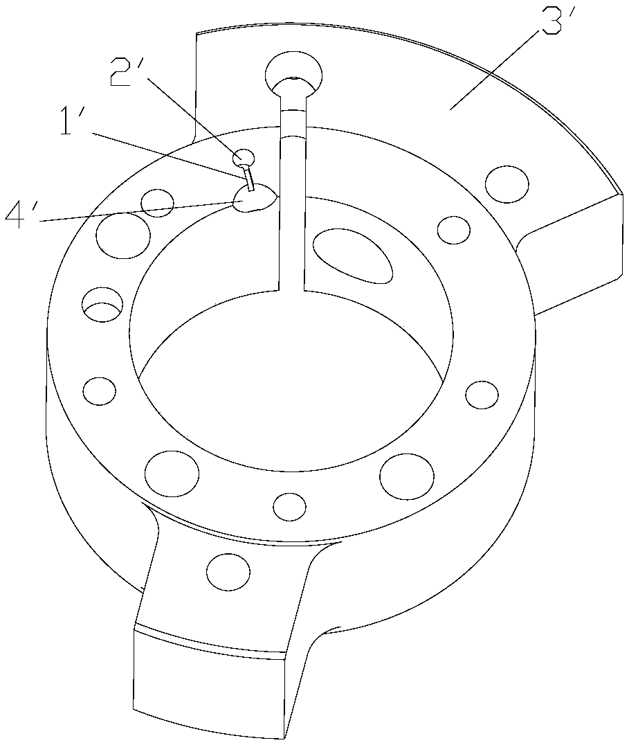
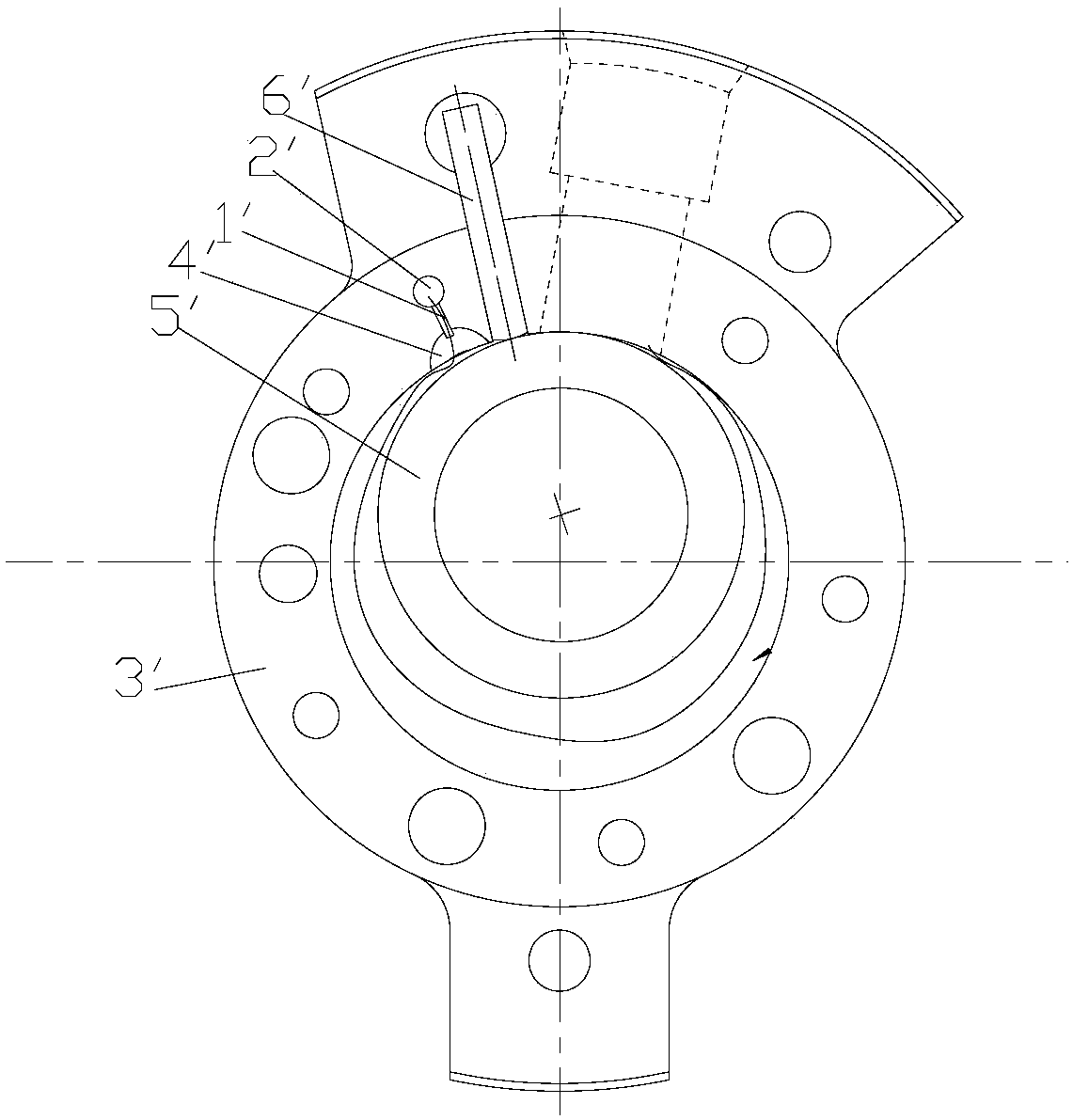
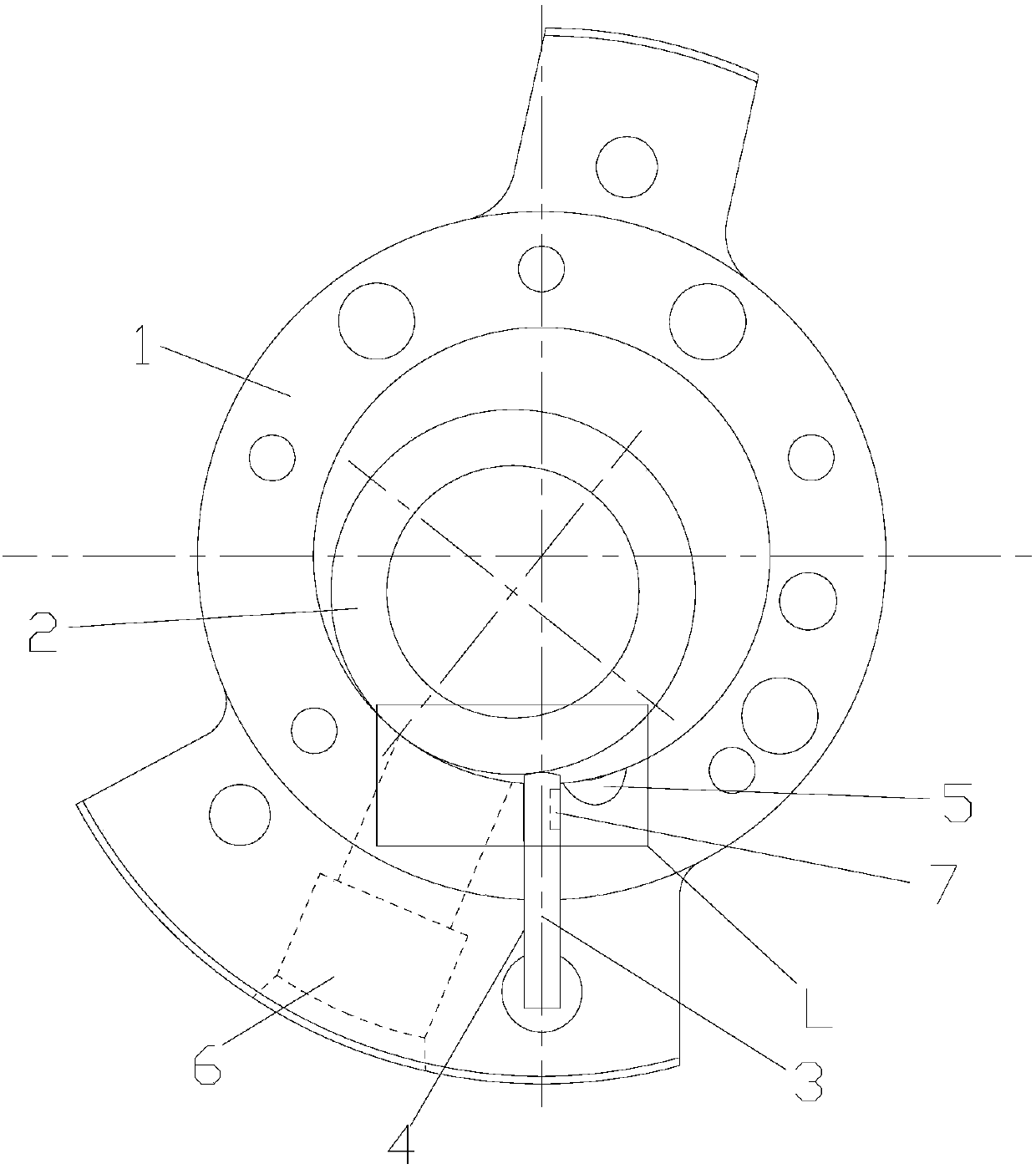
[0038] see in conjunction Figure 1 to Figure 17 As shown, according to the embodiment of the present invention, the pump body assembly includes a cylinder 1, a roller 2 and a slide 3, the roller 2 is rotatably arranged in the cylinder 1, and the cylinder 1 is provided with a slide groove 4 and an exhaust groove 5 and the suction port 6, the sliding piece 3 is slidably set in the sliding piece groove 4, one end of the sliding piece 3 abuts against the outer circumference of the roller 2, and the side of the sliding piece 3 facing the exhaust groove 5 is provided with a first muffler chamber 7. During one rotation cycle of the roller 2, the first muffler chamber 7 is not connected to the suction port 6.
[0039] When the pump body assembly is working, since the first muffler chamber 7 and the suction port 6 are not connected during the entire rotation cycle of the roller 2, high-pressure gas will be squeezed in from the compression chamber during the exhaust process of the comp...
PUM
 Abstract
Description
Claims
Application Information
 - R&D
- Intellectual Property
- Life Sciences
- Materials
- Tech Scout
- Unparalleled Data Quality
- Higher Quality Content
- 60% Fewer Hallucinations
Browse by: Latest US Patents, China's latest patents, Technical Efficacy Thesaurus, Application Domain, Technology Topic, Popular Technical Reports.
© 2025 PatSnap. All rights reserved.Legal|Privacy policy|Modern Slavery Act Transparency Statement|Sitemap|About US| Contact US: help@patsnap.com