

Testing device for measuring plane global frictional force vector field, and working method
A technology for measuring planes and test devices, applied in the field of aerodynamics, can solve the problems of high requirements for instrument design and installation, cumbersome measurement process, and inability to perform global measurement with friction force measurement technology. The effect of avoiding light interference and easy disassembly
- Summary
- Abstract
- Description
- Claims
- Application Information
AI Technical Summary
Problems solved by technology
Method used
Image

Examples
Embodiment Construction
[0033] In order to facilitate the understanding of those skilled in the art, the present invention will be further described below in conjunction with the embodiments and accompanying drawings, and the contents mentioned in the embodiments are not intended to limit the present invention.
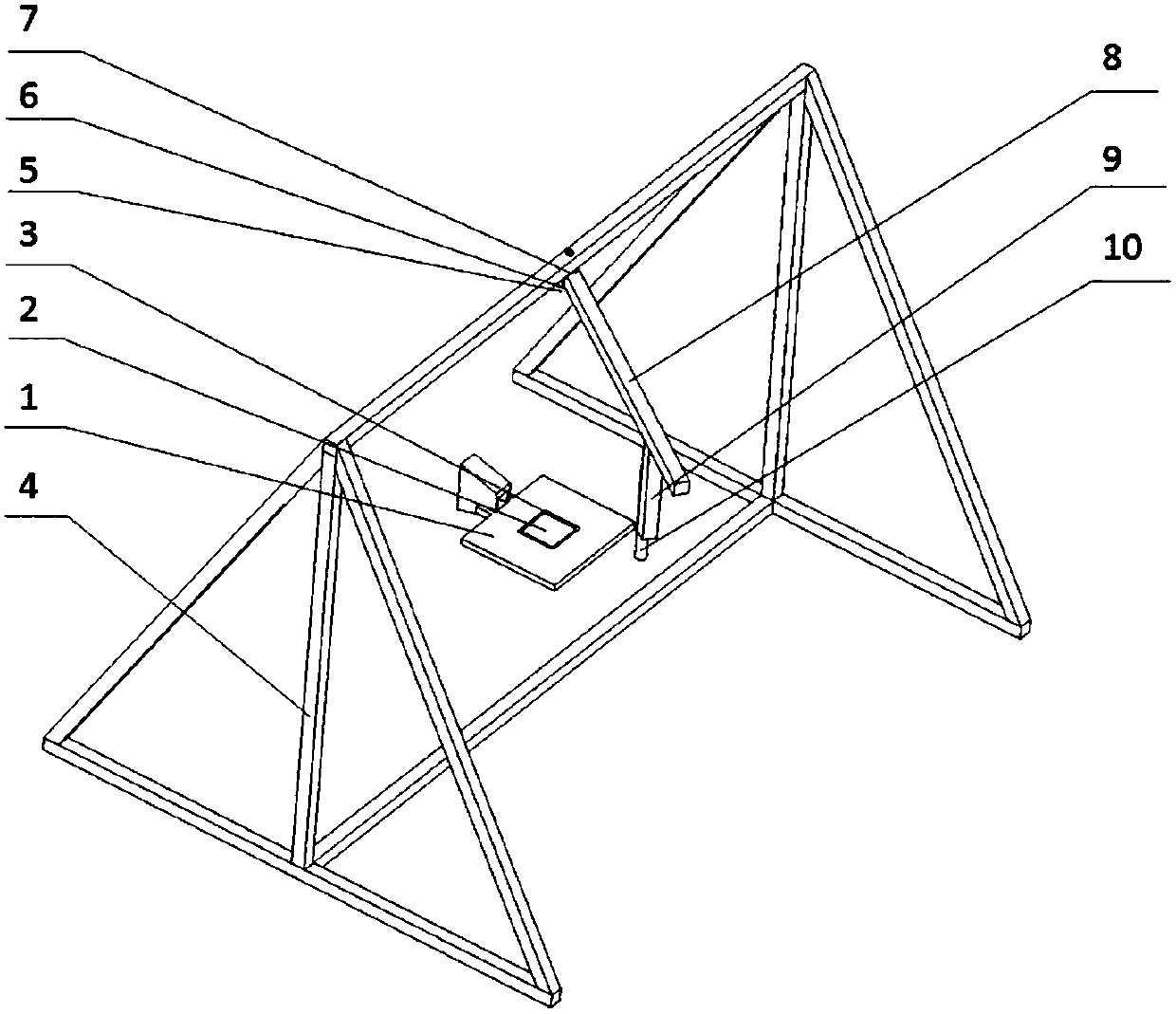
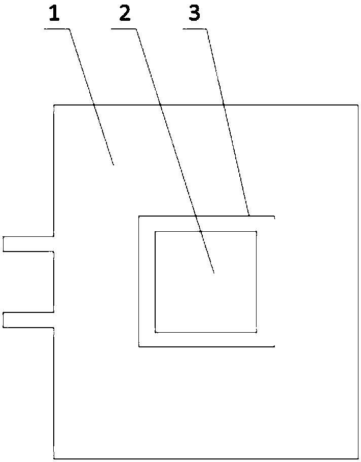
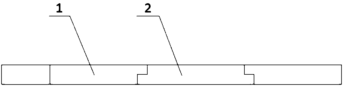
[0034] refer to figure 1 As shown, a test device for measuring the surface friction vector field of a flat plate of the present invention includes a downstream flat plate 1, a detachable blackened flat plate 2, a calibration line 3, a bracket 4, a light source 5, a movable hinge 6, and an angle plate 7 , rotatable cantilever 8, adjustable connecting rod 9, camera connecting bracket 10, hinge connecting part 11, wherein,
[0035] The downstream plate 1 is connected to the nozzle, and the connection is smooth and transitions to generate a flow field; the detachable blackened plate 2 is embedded in the test area of the downstream plate 1 to ensure that the upper surface of the detachable blac...
PUM
 Abstract
Description
Claims
Application Information