
Measuring circuit for electrolytic capacitor

A technology for measuring circuits and electrolytic capacitors, applied in the field of measuring circuits, can solve the problems of leakage, inconvenience of rapid judgment, poor measurement accuracy, etc., and achieve the effect of convenient use, good application prospects, and convenient rapid judgment.

Inactive Publication Date: 2018-01-19
苏州松挺材料科技有限公司
View PDF0 Cites 0 Cited by
  • Summary
  • Abstract
  • Description
  • Claims
  • Application Information

AI Technical Summary

Problems solved by technology

[0003] The purpose of the present invention is to overcome the problem that the existing electrolytic capacitors will leak during long-term storage, and the ca

Method used


Image

  • Measuring circuit for electrolytic capacitor

Examples


Embodiment Construction

[0015] The present invention will be further described below in conjunction with the accompanying drawings.

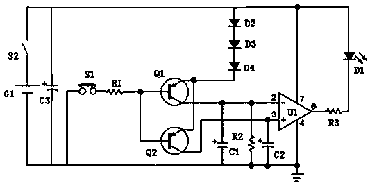
[0016] Such as figure 1 As shown, the measurement circuit for electrolytic capacitance of the present invention includes storage battery G1, transistor Q1, transistor Q2, operational amplifier U1 and light emitting diode D1,

[0017] The positive pole of the storage battery G1 is connected to the positive pole of the diode D2, the positive power input terminal of the operational amplifier U1, and the positive pole of the light-emitting diode D1 respectively, and the base pole of the transistor Q1 is connected to one end of the button S1 through a resistor R1. The other end of the button S1 is connected to the ground, the base of the transistor Q1 is also connected to the base of the transistor Q2, the emitter of the transistor Q1 is connected to the emitter of the transistor Q2, and the cathode of the diode D2 is connected to the The anode of the diode D3 is connected...


PUM


Abstract

The invention discloses a measuring circuit for an electrolytic capacitor. The measuring circuit comprises a storage battery G1, a transistor Q1, a transistor Q2, an operational amplifier U1 and a light-emitting diode D1. A reference capacitor and a to-be-measured capacitor are compared, and then the light-emitting diode D1 is turned on when the to-be-measured capacitor leaks seriously. Therefore,a user is reminded of not using the to-be-measured capacitor any more. The measuring circuit is convenient to use, easy in fast judgment, simple in capacitance, easy to implement and good in application prospect.

Description

technical field [0001] The invention relates to the technical field of measuring circuits, in particular to a measuring circuit for electrolytic capacitors. Background technique [0002] Electrolytic capacitors will leak during long-term storage. Before use, they need to be measured. Electrolytic capacitors with serious leakage will not be used, so as to affect the use effect of electrolytic capacitors. At present, a multimeter is used on the market to measure the capacitance of electrolytic capacitors, but the measurement accuracy is not good, and it is not convenient to quickly judge whether the electrolytic capacitor can be used. Contents of the invention [0003] The purpose of the present invention is to overcome the existing electrolytic capacitors, which may leak during long-term storage, and use a multimeter to measure the capacitance of the electrolytic capacitors, which has poor measurement accuracy and is not convenient for quick judgment. In the measurement ci...

Claims


Application Information

Patent Timeline
IPC IPC(8): G01R27/26
Inventor 周素华
Owner 苏州松挺材料科技有限公司
Learn More