Optical fingerprint sensing device with biomedical sensing function

A sensing device, biomedical technology, used in instruments, character and pattern recognition, computer parts, etc.

Active Publication Date: 2018-01-19
FOCALTECH ELECTRONICS
View PDF10 Cites 2 Cited by
  • Summary
  • Abstract
  • Description
  • Claims
  • Application Information

AI Technical Summary

Problems solved by technology

But in fact, there are still problems such as how to combine the two together, and how many pixels are needed to provide light intensity information to form a PPG signal.

Method used


Image

  • Optical fingerprint sensing device with biomedical sensing function
  • Optical fingerprint sensing device with biomedical sensing function
  • Optical fingerprint sensing device with biomedical sensing function

Examples


Embodiment Construction

[0018] The following will clearly and completely describe the technical solutions in the embodiments of the present invention with reference to the accompanying drawings in the embodiments of the present invention. Obviously, the described embodiments are only some, not all, embodiments of the present invention. Based on the embodiments of the present invention, all other embodiments obtained by persons of ordinary skill in the art without making creative efforts belong to the protection scope of the present invention.

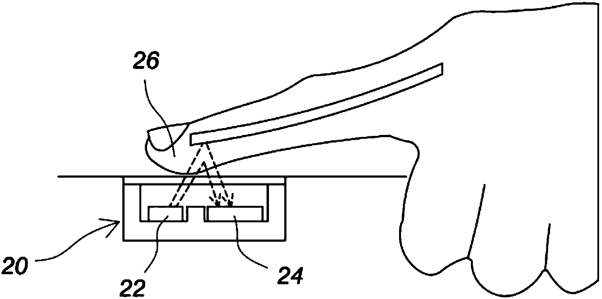
[0019] Since the optical fingerprint sensing device of the present invention can receive the fingerprint image in the fingerprint sensing mode, and can receive the signal strength in the biomedical sensing mode as a photo volume description (PPG) signal, so before explaining the technical features of the present invention Firstly, the design concept of selecting a local area for biomedical sensing mode in the present invention will be described.

[0020] For s...


PUM


Abstract

The invention discloses an optical fingerprint sensing device with a biomedical sensing function, and the device mainly comprises at least one light-emitting element which generates a light source, and an image sensing module. The image sensing module is provided with a plurality of sensing units, can receive the light reflected by fingers in a normal fingerprint sensing mode, and can transmit a measured brightness signal to the outside so as to obtain a fingerprint image. The image sensing module is provided with a local region, thereby enabling some sensing units of the plurality of sensingunits to be located in the local region at the same time. Moreover, the sensing units located in the local region form electrical connection through a first switch, so as to perform a biomedical sensing mode for measuring the light intensity signal of fingers. In addition, the time domain change of the light intensity signal is taken as a light volume description (PGG) signal for the subsequent biomedical application.

Description

technical field [0001] The invention relates to an optical fingerprint sensing technology, in particular to an optical fingerprint sensing device which can also have a biomedical sensing function. Background technique [0002] A common optical fingerprint sensor 10 usually uses a CMOS image sensor as a sensor for capturing images, and its basic structure is as follows: figure 1 As shown, one or more light emitting diodes 12 emit light to irradiate the surface of the finger to be tested, and then a high-resolution CMOS sensor 14 is used to receive fingerprint images. When the CMOS sensor 14 transmits an image, the brightness measured by each pixel in the CMOS sensor 14 will be transmitted immediately and sequentially until the entire image is transmitted, so as to obtain a faster image capture speed; but this sensor design Although it has the advantages of simple structure and fast image capture, in actual use, the entire image must be read each time before reading the next ...

Claims


Application Information

Patent Timeline
Patent Type & Authority Applications(China)
IPC IPC(8): G06K9/00
Inventor 刘至伟江文男郭瀚文
Owner FOCALTECH ELECTRONICS
Why Eureka
Try Eureka