Composite doctor blade chamber

A squeegee, combined technology, applied in the direction of bonding method, printing process, application, etc., can solve the problem of reducing printing quality, irritating workers, penetrating between the squeegee and the clamp rail, and the squeegee and the squeegee problems between cavities

Inactive Publication Date: 2018-01-19
TRESU
View PDF7 Cites 6 Cited by
  • Summary
  • Abstract
  • Description
  • Claims
  • Application Information

AI Technical Summary

Problems solved by technology

Even very small variations in this spacing between the doctor blade and the roller, on the order of a few microns, can result in uneven application of ink to the roller, reducing print quality
Additionally, in the area between the screws, ink may seep between the doctor blade and clamp rail and between the doctor blade and the doctor blade chamber, further enhancing the "flashing" effect and requiring frequent cleaning
Third, tools are needed to loosen and tighten screws
Failure to use this tool for replacement during work, for example due to a colleague misplacing the tool, can be a major source of irritation for the worker

Method used


Image

  • Composite doctor blade chamber
  • Composite doctor blade chamber
  • Composite doctor blade chamber

Examples


Embodiment Construction

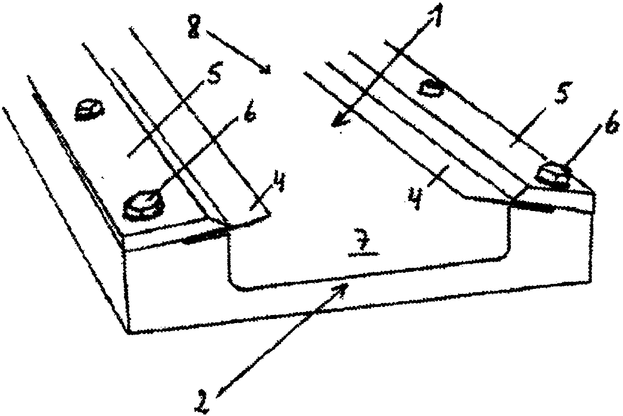
[0121] figure 1 is a perspective view of a part of a doctor blade chamber 1 according to the prior art. For illustration, the doctor blade chamber 1 is shown without an end cap, which normally seals the end 2 so that ink cannot flow out of the doctor blade chamber 1 . The doctor blade 4 sandwiched between the clamp rail 5 and the doctor blade chamber 1 is installed on the doctor blade chamber 1 . Screw the clamp rail 5 to the doctor blade chamber 1 with the bolt 6. The doctor blade chamber 1 together with the doctor blade 4 forms a wall of ink 7 . When the doctor blade cavity 1 is aligned with the ink transfer roller, the open channel 8 between the doctor blades 4 is closed.

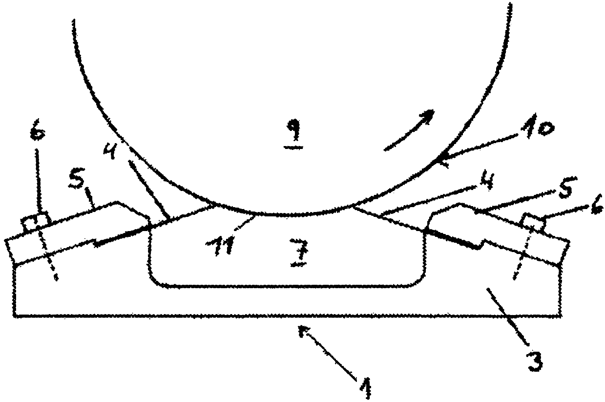
[0122] figure 2 A sectional view of a doctor blade chamber 1 and a transfer roller 9 according to the prior art is shown. When the two doctor blades 4 are in contact with the roller surface 10, the ink chamber 7 is substantially closed. When the ink transfer roller 9 rotates along its axis, the pa...


PUM


Abstract

A composite doctor blade chamber (1) for a doctor blade chamber system for rotary printing units, the doctor blade chamber (1) including a front side with an open channel (8), wherein the doctor bladechamber is made of two composite profiles, an open profile (30) with a front side and a back side and a closed profile (33) with a front side and a back side, wherein the front side (31) of the openprofile is joined with the back side of the closed profile (35), whereby is achieved low weight and high strength, high corrosion resistance, a cleaning-friendly surface, less waste of ink, nice appearance and an improved working environment. In addition it is an object of the invention to provide a doctor blade chamber system with the above mentioned advantages where replacement of doctor bladescan be performed faster, more easily and without use of tools.

Description

technical field [0001] The invention relates to a method for producing a composite doctor blade chamber comprising two composite profiles. [0002] The invention also relates to a combined doctor blade chamber for a doctor blade chamber system of a cylinder printing unit, the doctor blade chamber comprising a front side with an open channel. [0003] Furthermore, the invention relates to a doctor blade chamber system for a cylinder printing unit comprising a doctor blade chamber, a clamping rail and a doctor blade. [0004] Furthermore, the invention relates to the use of doctor blade chamber systems. Background technique [0005] In cylinder printing units for offset printing, flexographic printing and other kinds of printing, it is advantageous to use a system comprising a so-called doctor blade chamber. The doctor blade chamber is the ink container which is held tightly against the ink transfer roller by means of a so-called doctor blade which transfers the ink from the...

Claims


Application Information

Patent Timeline
Patent Type & Authority Applications(China)
IPC IPC(8): B41F31/02
CPCB41F31/027B41F35/008B41F9/1081B41F31/04B41P2200/12B29D22/00B29K2031/00B29K2063/00B29K2067/00B29K2307/04B29K2309/08B41N7/06B41N2207/10B41N2207/14C09J5/00
Inventor 杨·吉亚·拉森
Owner TRESU
Why Eureka
Try Eureka