Improved nasonry knife

The utility model relates to a technology for plastering knives and plastering tiles, which is applied in the field of plastering knives, and can solve the problems of inaccurate placement, cumbersome operation, easy spillage of cement, etc., and achieve the effects of lightening the workload, beautiful wall structure, and convenient construction operations.

Active Publication Date: 2018-01-23
徐州致诚会计服务有限公司
View PDF9 Cites 1 Cited by
  • Summary
  • Abstract
  • Description
  • Claims
  • Application Information

AI Technical Summary

Problems solved by technology

[0002] With the development of economy and urbanization, the construction of cities and villages is constantly accelerating, and various buildings have sprung up like mushrooms after a spring rain; masonry knives are the most commonly used construction tools when building walls, but the current The masonry knife is too simple and primitive, and it is extremely inconvenient to use: first, the amount of cement that can be picked up by the front end of the masonry knife is very small, and construction workers need to frequently pick mud and paint walls, which is cumbersome and inefficient; , the cement that is provoked is easy to spill during the moving process, resulting in waste of cement, and the dripping cement is easy to cause pollution and damage to the wall surface, which affects the flatness of the wall surface; On the upper surface, the cutter board needs to be turned over during operation. It is inconvenient to place the cement, and it is easy to place it in an inaccurate position. According to experience and visual inspection, it is easy to cause uneven thickness of cement layer, which will affect the firmness and aesthetics of the wall

Method used


Image

  • Improved nasonry knife
  • Improved nasonry knife
  • Improved nasonry knife

Examples


Embodiment

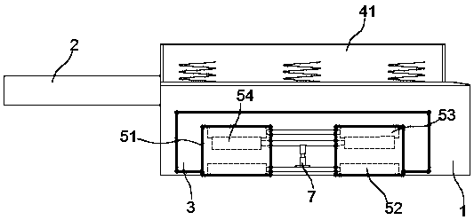
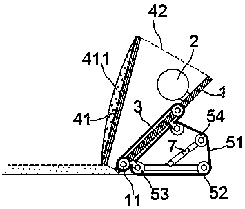
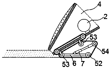
[0018] exist Figure 1 to Figure 3 In the shown embodiment, the improved masonry knife includes a knife plate 1 and a knife handle 2;

[0019] Two drive rollers 11 are embedded on the knife plate 1, the drive rollers 11 are parallel to the bottom edge of the knife plate 1, and a transmission belt 3 is installed between the two drive rollers 11, and the transmission belt 3 is connected from the knife plate The sides of 1 are exposed;

[0020] On one side of the knife plate 1, a collecting hopper 4 is fixedly arranged, and the outlet of the collecting hopper 4 is parallel to the bottom edge of the knife plate 1; the collecting hopper 4 includes a hard baffle plate 41 and a quality Soft connecting edge 42, the baffle plate 41 is opposite to the knife plate 1, a rubber layer 411 is attached to the outer surface of the baffle plate 41, and a buffer is installed between the inner plate surface of the baffle plate 41 and the knife plate 1. spring;

[0021] On the other side plate ...


PUM


Abstract

The invention relates to an improved nasonry knife comprising a knife plate and a knife handle. Transmission rollers are embedded into the knife plate and are parallel to the bottom edge of the knifeplate, and a transmission belt is mounted between the two transmission rollers and exposed from the two sides of the knife plate. A material collecting hopper is fixedly arranged on the plate face ofone side of the knife plate, and driving devices are mounted on the plate face of the other side of the knife plate and each comprise a driving belt, a wall face wheel, a plate face wheel and an adjusting wheel. A wheel shaft of each wall face wheel is connected to a wheel shaft of the corresponding plate face wheel through a support rod, and a limiting device is arranged between each support rodand the knife plate. The support rods are further provided with adjusting rods in a shaft-connection mode, and the adjusting wheels are arranged at the ends of the adjusting rods. The wall face wheels, the plate face wheels and the adjusting wheels are sleeved with the driving belts. The improved nasonry knife is novel in structure, convenient to operate and capable of ensuring the even thicknessof a cement layer and effectively improving the construction efficiency; and meanwhile it can be ensured that construction is clean and safe.

Description

technical field [0001] The invention relates to a building construction tool, in particular to a masonry knife. Background technique [0002] With the development of economy and urbanization, the construction of cities and villages is constantly accelerating, and various buildings have sprung up like mushrooms after a spring rain; masonry knives are the most commonly used construction tools when building walls, but the current The masonry knife is too simple and primitive, and it is extremely inconvenient to use: first, the amount of cement that can be picked up by the front end of the masonry knife is very small, and construction workers need to frequently pick mud and paint walls, which is cumbersome and inefficient; , the cement that is provoked is easy to spill during the moving process, resulting in waste of cement, and the dripping cement is easy to cause pollution and damage to the wall surface, which affects the flatness of the wall surface; On the upper surface, th...

Claims


Application Information

Patent Timeline
Patent Type & Authority Applications(China)
IPC IPC(8): E04G21/20
Inventor 沈炜
Owner 徐州致诚会计服务有限公司
Why Eureka
Try Eureka