Rotary compressor
A rotary compressor and compressor technology, applied in rotary piston machinery, rotary piston pumps, rotary piston/oscillating piston pump components, etc., can solve problems such as efficiency reduction and noise, and achieve suppression of efficiency reduction. Effect
- Summary
- Abstract
- Description
- Claims
- Application Information
AI Technical Summary
Problems solved by technology
Method used
Image

Examples
no. 1 example
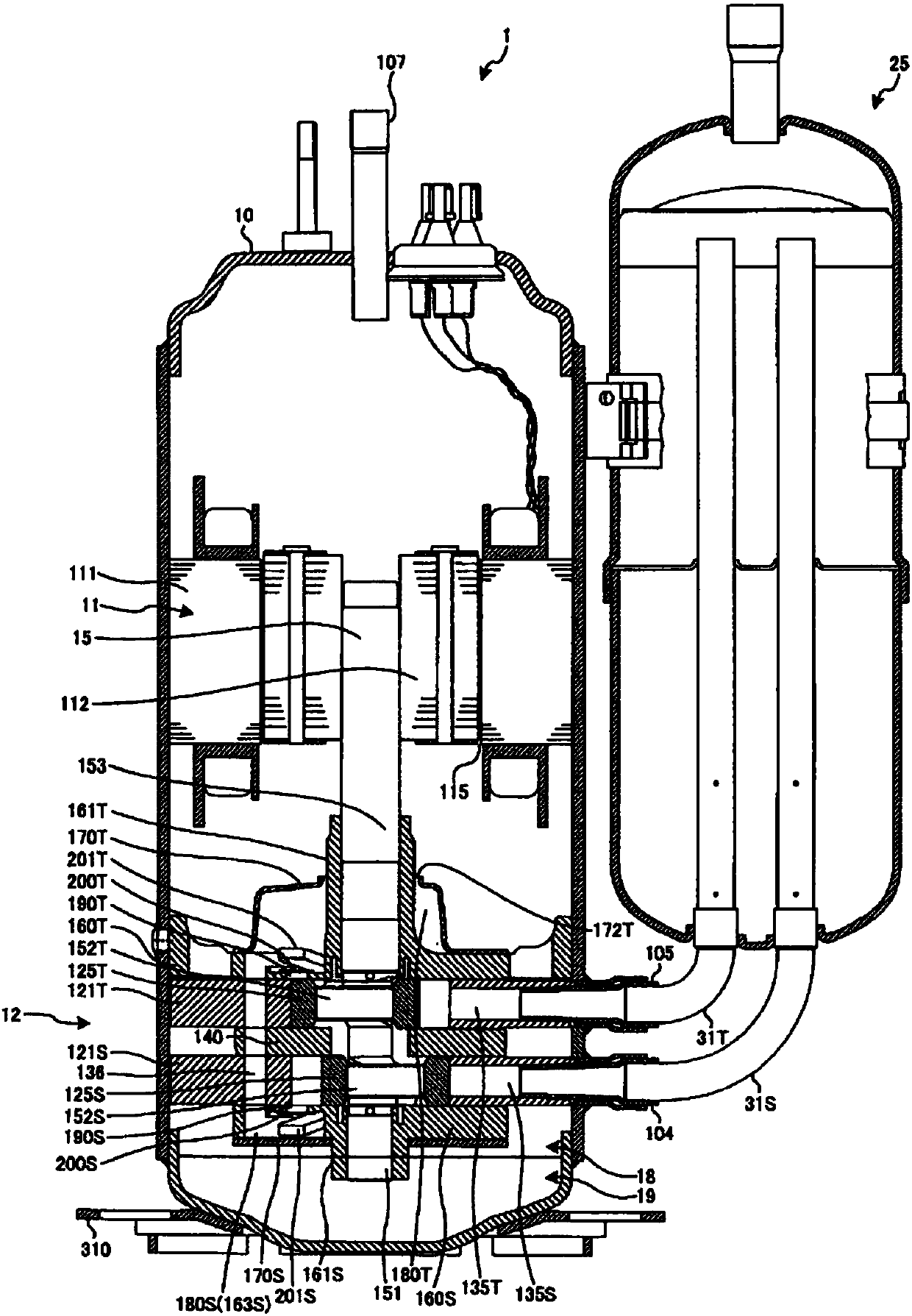
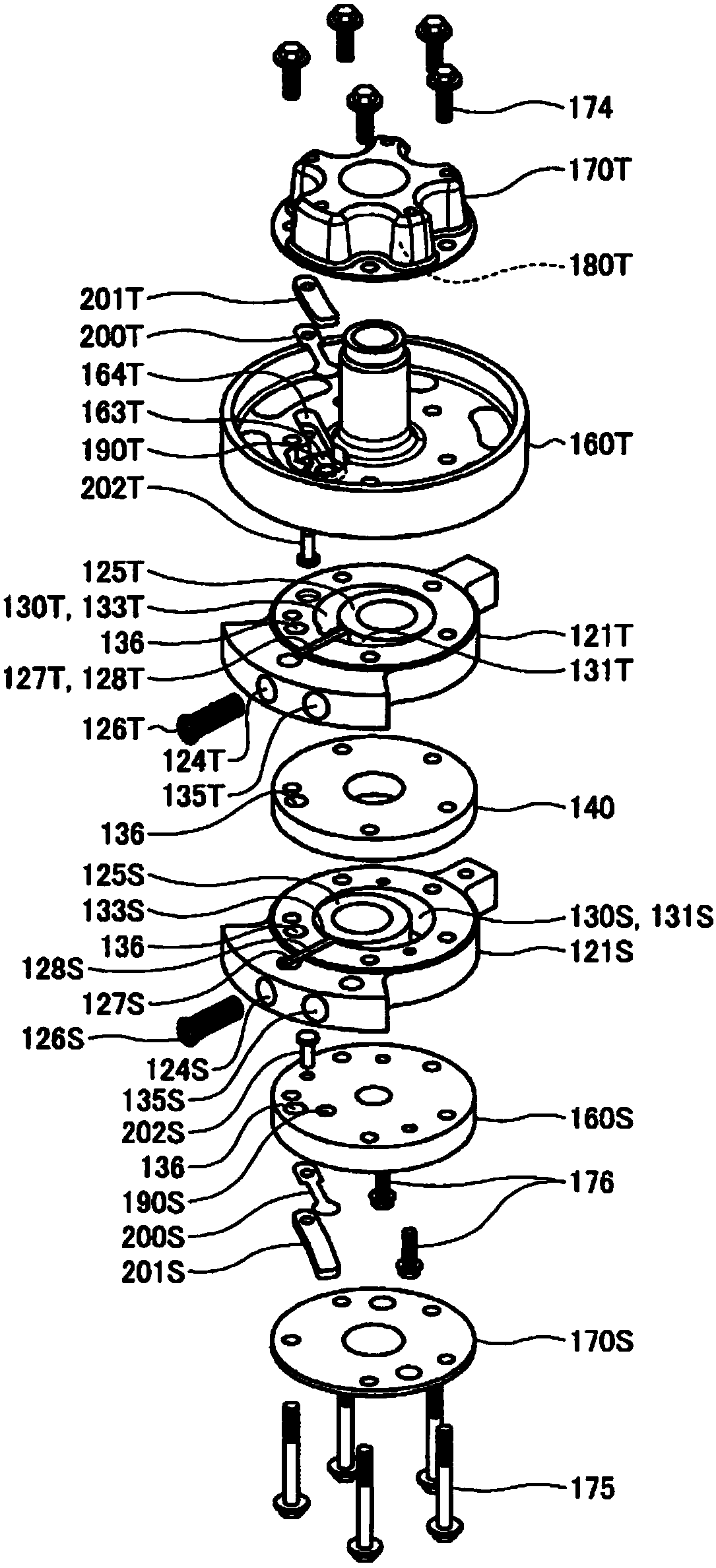
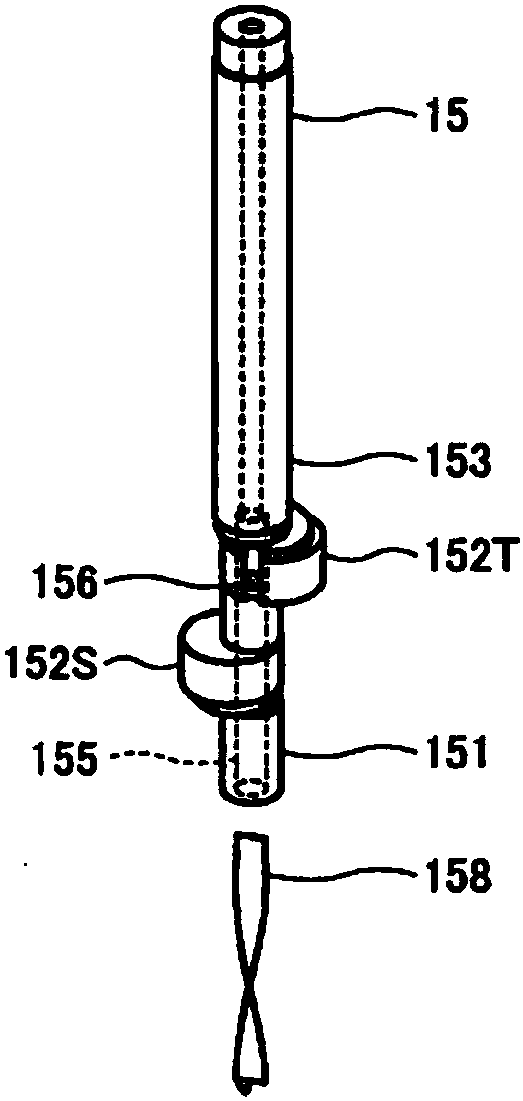
[0113] figure 1 It is a longitudinal sectional view showing the first embodiment of the rotary compressor of the present invention. figure 2 It is an exploded perspective view looking at the compression part of the rotary compressor of 1st Example from above. image 3 It is an exploded perspective view of the rotary shaft and the oil supply vane of the rotary compressor of the first embodiment seen from above.
[0114] Such as figure 1 As shown, the rotary compressor 1 includes: a compression unit 12 disposed at the lower portion of a closed vertical cylindrical compressor housing 10 , disposed above the compressor unit 12 , and drives the compression unit 12 via a rotary shaft 15 . The electric motor 11 and the vertical cylindrical accumulator 25 fixed to the side of the compressor housing 10 are included.
[0115] The liquid reservoir 25 passes through the upper suction pipe 105 and the upper L-shaped pipe 31T of the liquid reservoir and the upper suction chamber 131T of...
no. 2 example
[0145] Image 6 It is a longitudinal sectional view showing a lower discharge valve housing recess in which a lower discharge valve is mounted in the rotary compressor of the second embodiment. Such as Image 6 As shown, in the rotary compressor 1 of the second embodiment, the depth H from the lower discharge chamber recess 163S2 and the lower discharge valve housing recess 164S2 formed in the lower end plate 160S2 to the lower valve seat 191S is 2 It is shallower than the depth H from the lower discharge chamber recess 163S and the lower discharge valve housing recess 164S formed in the lower end plate 160S to the lower valve seat 191S in the rotary compressor 1 of the first embodiment. The lower end plate cover 170S2 has a recess 171S2 at a portion facing the front of the lower discharge valve retainer 201S, and accommodates a portion of the lower discharge valve retainer 201S protruding from the lower discharge chamber recess 163S2. The depth from the recess 171S2 to the ...
no. 3 example
[0148] Figure 7 It is a longitudinal sectional view showing a lower discharge valve housing recess in which the lower discharge valve is mounted in the rotary compressor of the third embodiment. Such as Figure 7 As shown, in the rotary compressor 1 of the third embodiment, a portion of the front portion of the lower discharge valve pressing plate 201S3 that is close to the lower end plate cover 170S is formed thinner than other portions. Thus, while ensuring the same opening degree as the lower discharge valve 200S of the rotary compressor 1 of the first embodiment, the depth H from the lower discharge chamber recess 163S3 and the lower discharge valve housing recess 164S3 to the lower valve seat 191S is ensured. 2 Same shallow as the second embodiment.
[0149] According to the structure of the rotary compressor 1 of the third embodiment described above, the volume of the lower end plate cover chamber 180S3 can be reduced by the volume of the concave portion 171S2 of the ...
PUM
 Abstract
Description
Claims
Application Information
 - R&D
- Intellectual Property
- Life Sciences
- Materials
- Tech Scout
- Unparalleled Data Quality
- Higher Quality Content
- 60% Fewer Hallucinations
Browse by: Latest US Patents, China's latest patents, Technical Efficacy Thesaurus, Application Domain, Technology Topic, Popular Technical Reports.
© 2025 PatSnap. All rights reserved.Legal|Privacy policy|Modern Slavery Act Transparency Statement|Sitemap|About US| Contact US: help@patsnap.com