
Oral cavity dilator

A dilator and oral cavity technology, which is applied in the field of medical devices, can solve problems such as no tongue depressing function, patient discomfort, and no device for controlling oral cavity opening and closing at a long distance, so as to achieve the effect of automatic control

Inactive Publication Date: 2018-01-26
高密市卫生学校
View PDF11 Cites 0 Cited by
  • Summary
  • Abstract
  • Description
  • Claims
  • Application Information

AI Technical Summary

Problems solved by technology

[0003] 1. It only has the function of pulling the mouth apart, but does not have the function of depressing the tongue. A tongue depressor must be used to press the patient's tongue
[0004] 2. Once the pulling force of the retractor is fixed, the positions of the upper and lower jaws are fixed. During the operation, the patient's mandible will exert force unconsciously, but because the position of the mandible is fixed, the patient feels uncomfortable. Comfortable
[0005] At the same time, the applicant found that all the existing oral expansion devices have not seen a device that can control the opening and closing of the oral cavity at a relatively long distance.

Method used


Image

  • Oral cavity dilator
  • Oral cavity dilator
  • Oral cavity dilator

Examples


Embodiment Construction

[0020] In order to make the objects and advantages of the present invention clearer, the present invention will be further described in detail below in conjunction with the examples. It should be understood that the specific embodiments described here are only used to explain the present invention, not to limit the present invention.

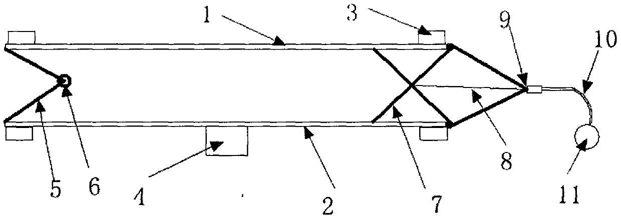
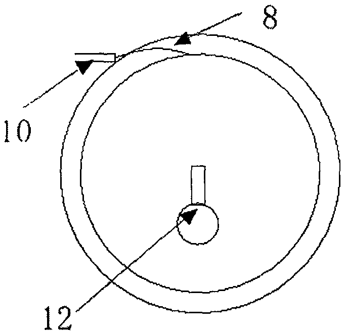
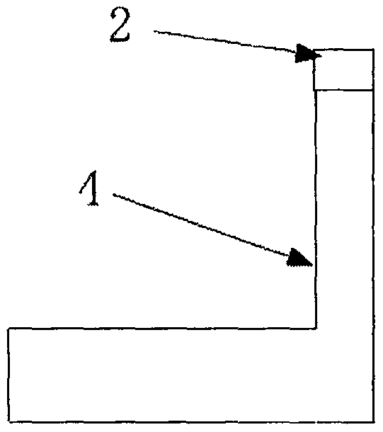
[0021] Such as Figure 1-Figure 3 As shown, the embodiment of the present invention provides an oral dilator, which includes an upper support plate 1 and a lower support plate 2, and two tooth pads 3 are respectively provided on the outer ends of the upper support plate 1 and the lower support plate 2, One end of the upper support plate 1 and the lower support plate 2 is connected by two movable frames A5, the other end is connected by two movable frames B7 and a V-shaped connector 9, and one end of the two movable frames A5 is connected with the upper support plate 1 respectively. One end of the lower support plate 2 is fixed, the other end is...


PUM


Abstract

The invention discloses an oral cavity dilator. The two ends of the outer side of an upper opening plate and the two ends of the outer side of a lower opening plate are each provided with two tooth pads; one ends of the upper opening plate and the lower opening plate are connected through two movable frames A, the other ends of the upper opening plate and the lower opening plate are connected through two movable frames B and a V-shaped connector, one ends of the two movable frames A are fixedly connected with one ends of the upper opening plate and the lower opening plate respectively, the other ends of the two movable frames A are connected through a connecting ring, the two movable frames B are arranged in a crossed mode, one ends of the two movable frames B are fixedly connected with one ends of the upper opening plate and the lower opening plate, and the other ends of the two movable frames B are connected with the inner side faces of the upper opening plate and the lower opening plate in a sliding mode; a traction steel wire is connected to the crossing point of the two movable frames B, a soft connection rod is installed at the front end of the V-shaped connector, the traction steel wire penetrates through the center of the V-shaped connector, and the soft connection rod is connected with a traction steel wire storage box. The oral cavity dilator can remotely control opening and closing of teeth, so that the oral cavity is in a movable open state; besides, the oral cavity dilator has a tongue pressing function and is convenient to use.

Description

technical field [0001] The invention relates to the field of medical instruments, in particular to an oral dilator. Background technique [0002] In the operation of intraoral restoration, it is usually necessary to use an oral distraction device to stretch the oral cavity and fix it. Most of the mouth stretching devices currently used in clinical practice are pull hooks. During use, the upper and lower jaws are pulled apart by the upper and lower hooks, so that the mouth can be stretched. The disadvantage of this pull hook is: [0003] 1. It only has the function of pulling the mouth apart, but does not have the function of depressing the tongue. A tongue depressor must be used to press the patient's tongue. [0004] 2. Once the pulling force of the retractor is fixed, the positions of the upper and lower jaws are fixed. During the operation, the patient's mandible will exert force unconsciously, but because the position of the mandible is fixed, the patient feels uncomfo...

Claims


Application Information

Patent Timeline
Patent Type & Authority Applications(China)
IPC IPC(8): A61B17/02
Inventor 门永宏
Owner 高密市卫生学校
Learn More