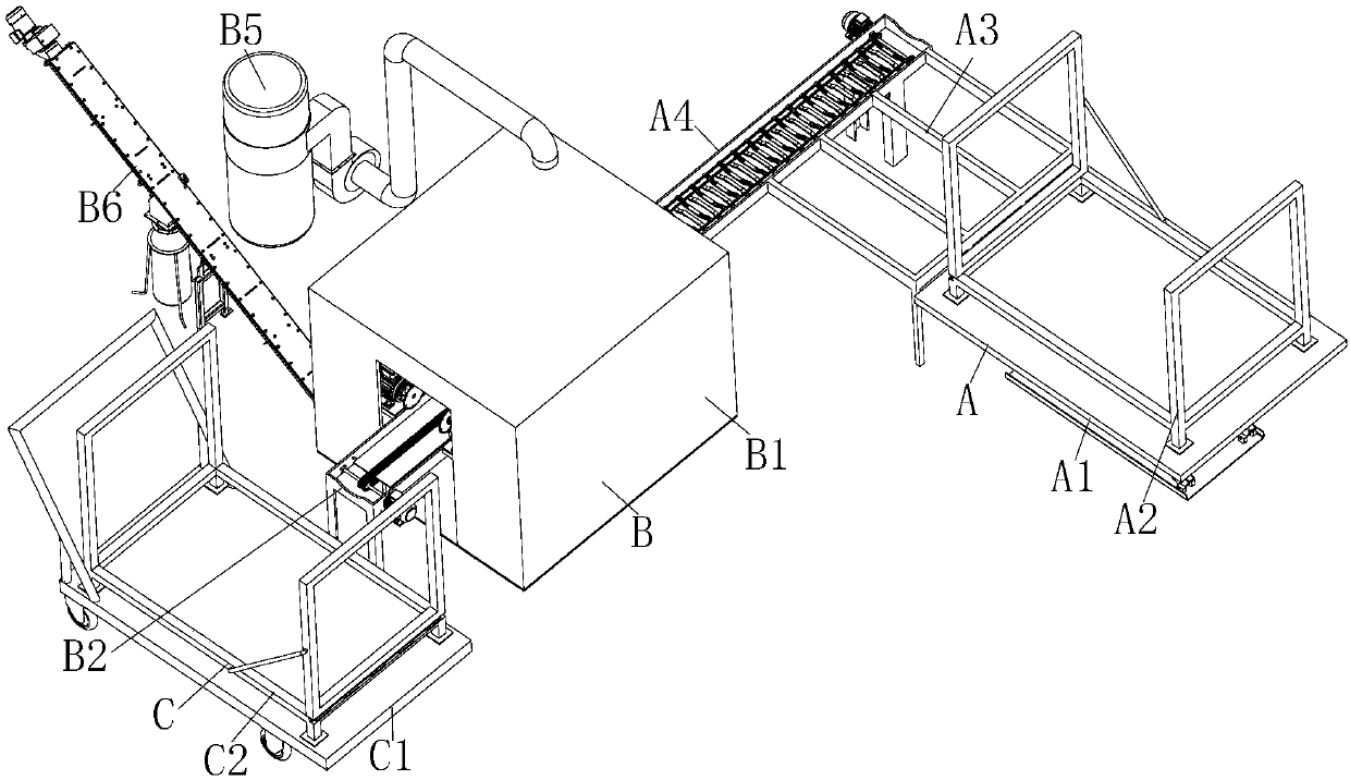
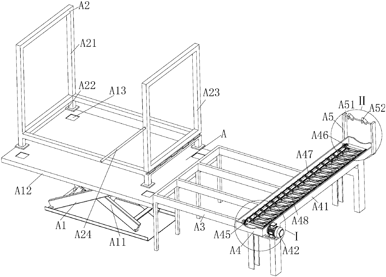
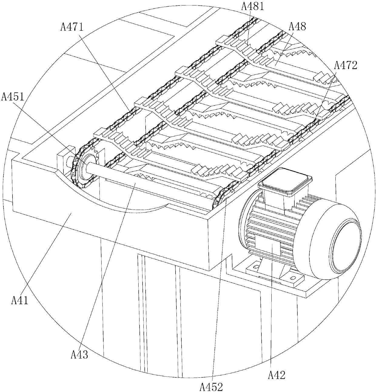
[0033] The present invention will be further described in detail with reference to the accompanying drawings and embodiments. The following embodiments are for explaining the present invention and the present invention is not limited to the following embodiments.
[0034] Examples.
[0035] See Figure 1 to Figure 9 As shown, it should be noted that the structure, ratio, size, etc. shown in the accompanying drawings in this specification are only used to match the content disclosed in the specification for those familiar with this technology to understand and read, and are not intended to limit the present invention The limited conditions that can be implemented do not have any technical significance. Any structural modification, proportional relationship change, or size adjustment should still be implemented without affecting the effects and objectives that can be achieved by the present invention. Within the scope covered by the technical content disclosed in the present invention. At the same time, if the terms such as "upper", "lower", "left", "right", "middle" and "one" are used in this manual, it is only for the convenience of description and is not used to limit the text. The scope of implementation of the invention, the change or adjustment of its relative relationship, without substantial changes to the technical content, shall also be regarded as the scope of implementation of the invention.
[0036] The multifunctional log automatic cutting machine in this embodiment includes a feeding device A, a cutting device B, and a conveying device C. The feeding device A is connected to one side of the cutting device B, and the transportation device C is placed on the other side of the cutting device B. On the other hand, the feeding device A includes a lifting table A1, a loading mechanism A2, a buffering table A3, a feeding and conveying mechanism A4, and a detection mechanism A5. The cutting device B includes a cutting device installation box B1, a cutting conveying mechanism B2, a cutting mechanism B3, and a spray Mechanism B4, dust collection mechanism B5 and debris collection mechanism B6. The conveying device C includes a transport vehicle C1 and a transport rack C2. The loading mechanism A2 is placed on the lifting platform A1. One side of the buffer platform A3 is in contact with the lifting platform A1. The other side of A3 is vertically connected to the feeding and conveying mechanism A4. The detection mechanism A5 is installed at the end of the feeding and conveying mechanism A4. The cutting and conveying mechanism B2 includes the feeding end of the cutting and conveying mechanism and the discharge end of the cutting and conveying mechanism. The material end, cutting mechanism B3 and spray mechanism B4 are all installed in the cutting device installation box B1, the discharge end of the cutting and conveying mechanism is exposed in the cutting device installation box B1, the cutting mechanism B3 is connected with the cutting and conveying mechanism B2, and the spray mechanism B4 is installed At the top of the cutting device installation box B1, and the spray mechanism B4 is located above the feed end of the cutting and conveying mechanism, the dust collection mechanism B5 is connected to the top of the cutting device installation box B1, and the debris collection mechanism B6 is connected to the bottom of the cutting device installation box B1 Connected, the transport rack C2 is placed on the transport vehicle C1, the feed end of the cutting and conveying mechanism is connected with the feed transport mechanism A4, and the transport vehicle C1 is placed on the side of the discharge end of the cutting and transport mechanism.
[0037] The loading mechanism A2 in this embodiment includes a loading fixing frame A21, a loading fixing frame base A22, a loading baffle A23 and a loading hook A24, and the feeding and conveying mechanism A4 includes a feeding and conveying mechanism mounting frame A41, a feeding drive motor A42, Feeding driving shaft A43, feeding driven shaft A44, feeding driving sprocket A45, feeding driven sprocket A46, feeding conveying chain A47 and non-slip conveying connecting piece A48, the loading baffle A23 is hinged with the loading fixing frame A21 , One end of the loading hook A24 is connected with the loading baffle A23, the other end of the loading hook A24 is connected with the loading fixing frame A21, the feeding drive motor A42, the feeding driving shaft A43 and the feeding driven shaft A44 are all installed in the feeding On the material conveying mechanism mounting frame A41, the motor shaft of the feeding drive motor A42 is connected to the feeding drive shaft A43, the feeding drive sprocket A45 is installed on the feeding drive shaft A43, and the feeding driven sprocket A46 is installed on the feeding On the driven shaft A44, the feeding drive sprocket A45 and the feeding driven sprocket A46 are connected by the feeding conveyor chain A47, and the non-slip conveyor connecting piece A48 is installed on the feeding conveyor chain A47. The cutting conveyor mechanism B2 includes a cutting conveyor frame B21, cutting and conveying motor B22, cutting and conveying driving shaft B23, cutting and conveying driven shaft B24, cutting and conveying driving sprocket B25, cutting and conveying driven sprocket B26, cutting and conveying chain B27, and cutting and conveying chain support plate B28, cutting mechanism B3 Including cutting mechanism mounting frame B31, cutting chute B32, cutting mechanism support plate B33, cutting slide B34, cutting drive motor B35, cutting saw blade B36, cutting sliding cylinder B37 and cutting sliding cylinder connecting plate B38, cutting and conveying drive sprocket B25 is installed on the cutting and conveying driving shaft B23, the cutting and conveying driven sprocket B26 is installed on the cutting and conveying driven shaft B24, and the cutting and conveying driving sprocket B25 and the cutting and conveying driven sprocket B26 are connected by the cutting and conveying chain B27, cutting and conveying The chain support plate B28 is installed on the cutting conveyor frame B21, the cutting conveyor chain B27 is placed on the cutting conveyor chain support plate B28, the cutting conveyor chain B27 is provided with positioning pins B29 on both sides, and the cutting mechanism mounting frame B31 is perpendicular to the cutting conveyor frame B21 The cutting mechanism mounting frame B31 is located in the cutting device housing B11, the cutting chute B32 is set on the cutting mechanism mounting frame B31, the cutting slide B34 is installed on the bottom surface of the cutting mechanism support plate B33, and the cutting slide B34 is embedded in the cutting chute In B32, the cutting drive motor B35 and the cutting sliding cylinder connecting plate B38 are installed on the top surface of the cutting mechanism support plate B33, the cutting saw blade B36 is installed on the motor shaft of the cutting drive motor B35, and the cylinder of the cutting sliding cylinder B37 is installed On the cutting mechanism mounting frame B31, the piston rod of the cutting sliding cylinder B37 is connected to the cutting sliding cylinder connecting plate B38, one side of the cutting conveyor frame B21 is connected to the feeding conveyor mechanism mounting frame A41, and the transport truck C1 is placed on the cutting conveyor frame B21 The other side.
[0038] The lifting platform A1 in this embodiment includes a lifting base A11, a lifting plate A12, and a loading mechanism installation groove A13. The lifting plate A12 is installed on the lifting base A11, and the loading mechanism installation groove A13 is provided on the top surface of the lifting plate A12. A21 is fixed on the loading fixture base A22, and the loading fixture base A22 is embedded in the loading mechanism installation slot A13; the cutting device installation box B1 includes the cutting device cover B11, the cutting device bottom plate B12, the suction port B13 and the chip discharge port B14, cutting The device bottom plate B12 is installed at the bottom of the cutting device cover B11, the air suction port B13 is located on the top of the cutting device cover B11, the chip discharge port B14 is located on the cutting device bottom plate B12, and one end of the cutting conveyor frame B21 is installed in the cutting device cover B11. The other end of the cutting conveyor frame B21 is exposed from the cutting device cover B11. The cutting conveyor motor B22, the cutting conveyor drive shaft B23 and the cutting conveyor driven shaft B24 are all installed on the cutting conveyor frame B21. The motor shaft of the cutting conveyor motor B22 is connected to the cutting conveyor. The driving shaft B23 is connected, and the cutting and conveying motor B22 is located outside the outer cover B11 of the cutting device.
[0039] The detection mechanism A5 in this embodiment includes a detection mechanism mounting frame A51 and an infrared detector A52. The detection mechanism mounting frame A51 is mounted on the end of the feeding and conveying mechanism mounting frame A41, and the infrared detector A52 is mounted on the detection mechanism mounting frame A51.
[0040] The spraying mechanism B4 in this embodiment includes a spraying pipe B41 and a spraying head B42. The spraying pipe B41 is installed on the top of the cutting device housing B1, and the spraying head B42 is installed on the spraying pipe B41; the dust collecting mechanism B5 includes a suction pipe B51 , Suction fan B52, exhaust pipe B53 and dust bag B54, one end of the suction pipe B51 is connected to the suction port B13, the other end of the suction pipe B51 is connected to the inlet of the suction fan B52, and one end of the exhaust pipe B53 is connected to The air outlet of the suction fan B52 is connected, and the other end of the exhaust pipe B53 is connected to the dust bag B54; the debris collection mechanism B6 includes screw elevator B61, screw elevator inlet B62, screw elevator discharge outlet B63, and crusher Chip collection bag B64 and chip collection bag holder B65, screw elevator feed inlet B62 is installed at the lower end of screw elevator B61, screw elevator discharge port B63 is installed at the upper end of screw elevator B61, screw elevator feed inlet B62 is connected with the debris discharge port B14, the debris collection bag B64 and the debris collection bag holder B65 are both located below the screw elevator discharge port B63, and the debris collection bag B64 is installed on the debris collection bag holder B65.
[0041] The feeding drive sprocket A45 in this embodiment includes the No. 1 feeding drive sprocket A451 and the No. 2 feeding drive sprocket A452, and the feeding driven sprocket A46 includes the No. 1 feeding driven sprocket A461 and the No. 2 feeding driven sprocket. The feeding driven sprocket A462, the feeding conveyor chain A47 include the No. 1 feeding conveyor chain A471 and the No. 2 feeding conveyor chain A472, the No. 1 feeding drive sprocket A451 and the No. 2 feeding drive sprocket A452 are respectively installed in On both sides of the feeding drive shaft A43, the No. 1 feeding driven sprocket A461 and the No. 2 feeding driven sprocket A462 are installed on both sides of the feeding driven shaft A44, and the No. 1 feeding driving sprocket A451 and The No. 1 feeding driven sprocket A461 is connected by the No. 1 feeding conveyor chain A471, the No. 2 feeding driving sprocket A452 and the No. 2 feeding driven sprocket A462 are connected by the No. 2 feeding conveyor chain A472, and the non-slip conveying connection One end of the piece A48 is connected with the No. 1 feeding conveyor chain A471, and the other end of the anti-skid conveying connecting piece A48 is connected with the No. 2 feeding conveyor chain A472.
[0042] The cutting mechanism mounting frame B31 in this embodiment includes the No. 1 cutting mechanism mounting frame and the No. 2 cutting mechanism mounting frame. The cutting chute B32 includes the No. 1 cutting chute and the No. 2 cutting chute. The cutting mechanism pallet B33 includes the No. 1 cutting mechanism. Cutting mechanism pallet and No. 2 cutting mechanism pallet, cutting slide B34 includes No. 1 cutting slide and No. 2 cutting slide, cutting drive motor B35 includes No. 1 cutting drive motor and No. 2 cutting drive motor, cutting saw blade B36 Including No. 1 cutting saw blade and No. 2 cutting saw blade. Cutting sliding cylinder B37 includes No. 1 cutting sliding cylinder and No. 2 cutting sliding cylinder. Cutting sliding cylinder connecting plate B38 includes No. 1 cutting sliding cylinder connecting plate and No. 2 cutting sliding cylinder Connecting plate, the No. 1 cutting mechanism mounting frame is installed vertically on one side of the cutting conveyor frame B21, the No. 2 cutting mechanism mounting frame is vertically installed on the other side of the cutting conveyor frame B21, and the No. 1 cutting chute is installed on the first cutting mechanism. On the frame, the No. 2 cutting slide is installed on the No. 2 cutting mechanism mounting frame, the No. 1 cutting slide is installed on the bottom surface of the No. 1 cutting mechanism pallet, and the No. 2 cutting slide rail is installed on the bottom surface of the No. 2 cutting mechanism pallet. The No. 1 cutting slide is embedded in the No. 1 cutting chute, the No. 2 cutting slide is embedded in the No. 2 cutting chute, the No. 1 cutting drive motor and the No. 1 cutting sliding cylinder connecting plate are both installed on the No. 1 cutting mechanism support plate The top surface of the No. 2 cutting drive motor and the No. 2 cutting sliding cylinder connecting plate are installed on the top surface of the No. 2 cutting mechanism support plate, the No. 1 cutting saw blade is installed on the motor shaft of the No. 1 cutting drive motor, and the No. 2 cutting The saw blade is installed on the motor shaft of the No. 2 cutting drive motor, the cylinder of the No. 1 cutting sliding cylinder is installed on the No. 1 cutting mechanism mounting frame, and the piston rod of the No. 1 cutting sliding cylinder is connected with the connecting plate of the No. 1 cutting sliding cylinder. The cylinder barrel of the No. 2 cutting sliding cylinder is installed on the No. 2 cutting mechanism mounting frame, and the piston rod of the No. 2 cutting sliding cylinder is connected with the connecting plate of the No. 2 cutting sliding cylinder.
[0043] In this embodiment, the feeding and conveying mechanism mounting frame A41 is provided with feeding semicircular grooves at both ends, and the feeding semicircular groove is provided in the middle of the feeding and conveying mechanism mounting frame A41, and the feeding semicircular recess is The groove is matched with the non-slip conveying connector A48; both ends of the cutting conveyor frame B21 are provided with cutting semicircular grooves, and the cutting semicircular groove is arranged in the middle of the cutting conveyor frame B21, and the diameter of the feeding semicircular groove is the same as The cut semicircular grooves have the same diameter.
[0044] In this embodiment, the middle part of the non-slip conveying connector A48 is recessed downward, the upper surface of the non-slip conveying connector A48 is provided with non-slip conveying teeth A481, and the non-slip conveying teeth A481 are arranged on both sides of the non-slip conveying connector A48. The shape of A481 is triangular, and the material of the non-slip conveying connector A48 is rubber; the top surface of the buffer table A3 is flush with the top surface of the feeding and conveying mechanism mounting frame A41; the feeding device A also includes a pit, and the lifting seat A11 is installed in Inside the pit; the cutting conveyor chain B27 includes a cutting conveyor chain conveyor section B271 and a cutting conveyor chain circulation section B272. The cutting conveyor chain conveyor section B271 is placed on the cutting conveyor chain support plate B28; the rear end of the cutting device installation box B1 is provided with a curtain .
[0045] The cutting method of the multifunctional log automatic cutting machine in this embodiment is characterized in that the cutting method is as follows:
[0046] Step 1: Place the wood to be processed on the loading mechanism A2, and place the wood loading mechanism A2 on the lifting platform A1 by a forklift, and insert the loading fixture base A22 in the loading mechanism installation slot A13, and pass the lifting platform A1 Raise the wood loading mechanism A2 to be flush with the buffer table A3;
[0047] Step 2: Open the loading hook A24, turn the loading baffle A23, unload the wood to be processed in the loading mechanism A2 to the buffer table A3, and when the wood to be processed is clamped together during the unloading process, pass the loading hook A24 Hook the clamped wood to be processed;
[0048] The third step: After the wood to be processed rolls down on the non-slip conveying connector A48, the length and diameter of the wood to be processed are detected by the infrared detector A52, and the detected signal is fed back to the control system and passed through the spray mechanism B4 Spray the wood to be processed, and the control system adjusts the cutting mechanism B3 according to the detected signal;
[0049] The fourth step: transport the wood to be processed that rolls down on the non-slip conveyor connector A48 to the cutting conveyor chain B27 through the feeding and conveying mechanism A4, and cut the wood to be processed on the cutting conveyor chain B27;
[0050] Step 5: When cutting, collect the dust generated in the cutting process through the dust collection mechanism B5, collect the debris generated in the cutting process through the debris collection mechanism B6, and place the cut wood transport rack C2 on it, And transported away by transporter C1.
[0051] In the third step of this embodiment, the control system adjusts the No. 1 cutting saw blade and the No. 2 cutting saw by controlling the expansion and contraction of the No. 1 cutting sliding cylinder and the No. 2 cutting sliding cylinder according to the detected diameter of the wood to be processed. The relative distance of the slices.
[0052] In addition, it should be noted that, in the specific embodiments described in this specification, the shapes and names of the parts and components may be different, and the above content described in this specification is merely an example of the structure of the present invention. All equivalent changes or simple changes made according to the structure, features and principles described in the concept of the patent of the present invention are included in the protection scope of the patent of the present invention. Those skilled in the art to which the present invention pertains can make various modifications or additions to the specific embodiments described or substitute similar methods, as long as they do not deviate from the structure of the present invention or exceed the scope defined by the claims. All should belong to the protection scope of the present invention.