Large-curvature aircraft fuselage assembly double-track positioner unit
An aircraft fuselage and locator technology, which is applied in aircraft assembly, workpiece clamping devices, manufacturing tools, etc., can solve the problems of limited installation space for locators, heavy workload for regular inspection and repair, and inconvenient maintenance, and reduces inspection and maintenance costs. Frequency and number of repairs, the effect of reducing maintenance costs and prolonging service life
- Summary
- Abstract
- Description
- Claims
- Application Information
AI Technical Summary
Problems solved by technology
Method used
Image

Examples
Embodiment 1
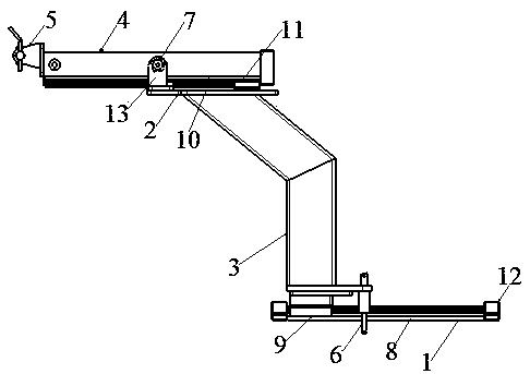
[0030] A large-curvature aircraft fuselage assembly double-rail locator unit, including a first mounting seat 1 installed on a tooling platform, a column 3 installed at the free end of the first mounting seat 1, a second mounting seat 2 arranged on the top of the column 3, The cantilever 4 arranged on the second mount 2;
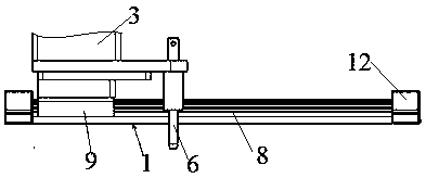
[0031] Such as image 3 As shown, the column 3 is slidably connected with the first mounting seat 1 through a first sliding mechanism, and the first sliding mechanism includes a first guide rail 8 fixedly installed on the first mounting seat 1, a first guide rail 8 installed at the bottom of the column 3 A sliding block 9; the column 3 is slidably connected with the first guide rail 8 through the first sliding block 9, so that the column 3 can slide back and forth on the first mounting seat 1; the column 3 is fixedly provided with a positioning pin 6;
[0032] A cantilever 4 is installed on the second mounting base 2, and the cantilever 4 is slidably connec...
Embodiment 2
[0038]This embodiment is further optimized on the basis of Embodiment 1. The first mounting seat 1 and the second mounting seat 2 are arranged in parallel, and the first guide rail 8 and the second guide rail 10 are vertically arranged, so that the positioner can be realized front and rear, left and right Position adjustment, the locator can flexibly adjust the position according to the needs, which improves the degree of freedom of the locator and effectively improves the efficiency of tooling assembly.
[0039] Other parts of this embodiment are the same as those of Embodiment 1, so they will not be repeated here.
Embodiment 3
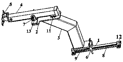
[0041] This embodiment is further optimized on the basis of embodiment 1, as figure 1 , figure 2 As shown, the column 3 includes two sections, and the sections are fixedly connected between the sections. A section of the column 3 is vertically arranged on the first mounting seat 1, and this section is connected to the first rail 8 through the slider mechanism of the first guide rail 8. The mounting base 1 is slidingly connected; the other section of the column 3 is inclined according to the needs of assembly, and is slidingly connected with the second mounting base 2 through the second guide rail 10 slider mechanism; the first mounting base 1 and the second mounting base 2 are arranged in parallel, the positioner can realize front and rear adjustment; both ends of the first guide rail 8 are provided with stoppers 12, which can prevent the first sliding block 9 from sliding out of the first mounting seat 1.
[0042] The invention adjusts the size and angle of the column 3 acc...
PUM
 Abstract
Description
Claims
Application Information
 - R&D
- Intellectual Property
- Life Sciences
- Materials
- Tech Scout
- Unparalleled Data Quality
- Higher Quality Content
- 60% Fewer Hallucinations
Browse by: Latest US Patents, China's latest patents, Technical Efficacy Thesaurus, Application Domain, Technology Topic, Popular Technical Reports.
© 2025 PatSnap. All rights reserved.Legal|Privacy policy|Modern Slavery Act Transparency Statement|Sitemap|About US| Contact US: help@patsnap.com