Electric valve

A technology of electric valves and spools, which is applied in the direction of valve lifts, valve devices, valve details, etc., and can solve problems such as large loads of spools

Active Publication Date: 2021-10-26
SAGINOMIYA SEISAKUSHO INC
View PDF9 Cites 0 Cited by
  • Summary
  • Abstract
  • Description
  • Claims
  • Application Information

AI Technical Summary

Problems solved by technology

In this fluid control valve, from the background of rationalization of control equipment such as integrating a plurality of electric valves used for flow control into one, it is desired to have a large diameter and to exhibit good operability even when a high pressure difference occurs. However, in terms of flow control with a relatively large caliber, compared to the thrust of the screw generated by the torque of the magnet, the load on the spool due to the pressure difference is large, and a large driving force is required to move the spool.

Method used


Image

  • Electric valve
  • Electric valve
  • Electric valve

Examples


Embodiment Construction

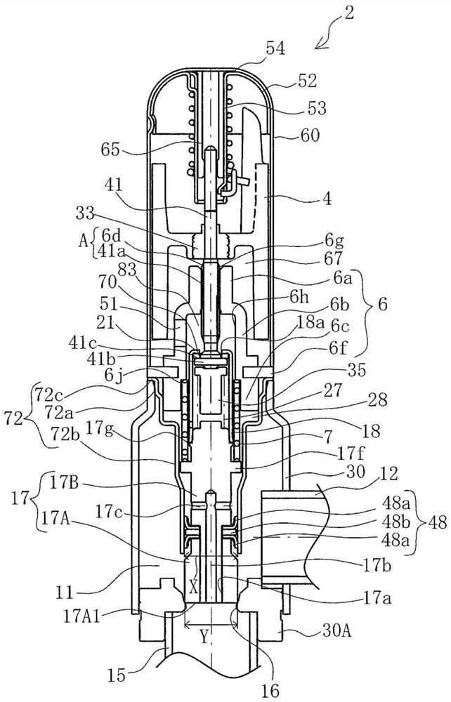
[0066] Hereinafter, an electric valve according to an embodiment of the present invention will be described with reference to the drawings. figure 1 It is a sectional view showing the electric valve 2 of the embodiment. Also, in this specification, "upper" and "lower" are used in figure 1 specified in the state. That is, the rotor 4 is located above the spool 17 .

[0067] In this electric valve 2 , a valve main body 30 is integrally connected by welding or the like below the opening side of a non-magnetic cylindrical cup-shaped housing 60 .

[0068] Here, the valve main body 30 is a press-formed product produced by press-working a metal material such as a stainless steel plate, and has a valve chamber 11 inside. In addition, a first pipe joint 12 made of stainless steel or copper that directly communicates with the valve chamber 11 is fixedly attached to the valve main body 30 . Further, a valve seat member 30A having a circular cross section and having a valve port 16 ...


PUM


Abstract

The invention provides an electric valve with high-precision flow control. The electric valve converts the rotary motion of the rotor into a linear motion through the screw connection of the external threaded part and the internal threaded part. A back pressure chamber is provided on the upper side, and the pressure in the valve port is introduced into the back pressure chamber. The electric valve is provided with an urging spring for urging the above-mentioned external thread member. The surface on one side of the thread is in contact with the surface on the other side of the thread formed on the female thread member.

Description

technical field [0001] The present invention relates to electric valves used in refrigeration cycles and the like. Background technique [0002] Conventionally, fluid control valves used in large cabinet air conditioners and refrigeration equipment are known (for example, refer to Patent Document 1). In this fluid control valve, from the background of rationalization of control equipment such as integrating a plurality of electric valves used for flow control into one, it is desired to have a large diameter and to exhibit good operability even when a high pressure difference occurs. However, in terms of flow control with a relatively large caliber, compared to the thrust of the screw generated by the torque of the magnet, the load on the spool due to the pressure difference is large, and a large driving force is required to move the spool. . [0003] Therefore, in order to improve the operability of the spool, a pressure balance mechanism described below is employed. For ...

Claims


Application Information

Patent Timeline
Patent Type & Authority Patents(China)
IPC IPC(8): F16K1/02F16K1/32F16K31/04F16K41/02F25B41/20F25B41/30
CPCF16K31/04Y02B30/70F25B41/35
Inventor 北见雄希石黑元康田边珠实
Owner SAGINOMIYA SEISAKUSHO INC
Why Eureka
Try Eureka