
Novel extractor hood

A technology for range hood and range hood, applied in the field of range hood, can solve the problems of high mold cost, serious homogeneity, inability to open high-end market, etc., and achieve the effect of novel and unique appearance and lower mold cost.

Pending Publication Date: 2018-01-26
中山市百事特电器有限公司
View PDF1 Cites 0 Cited by
  • Summary
  • Abstract
  • Description
  • Claims
  • Application Information

AI Technical Summary

Problems solved by technology

[0003] In the prior art, the range hood, especially the top-suction type range hood, is formed by stretching and stamping a metal plate integrally. The cost of the mold is very high, and the manufactured range hood is homogeneous. Seriously, can't open the high-end market

Method used


Image

  • Novel extractor hood
  • Novel extractor hood
  • Novel extractor hood

Examples


no. 1 example

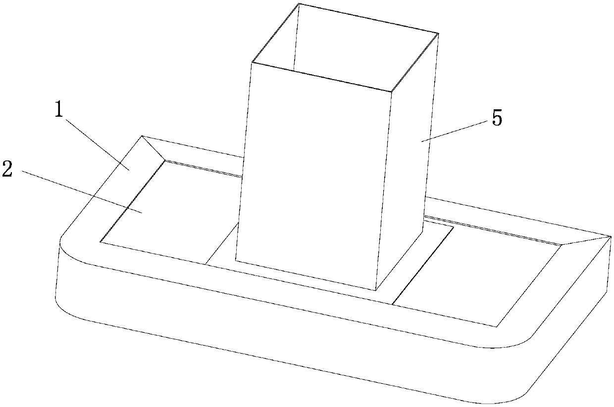
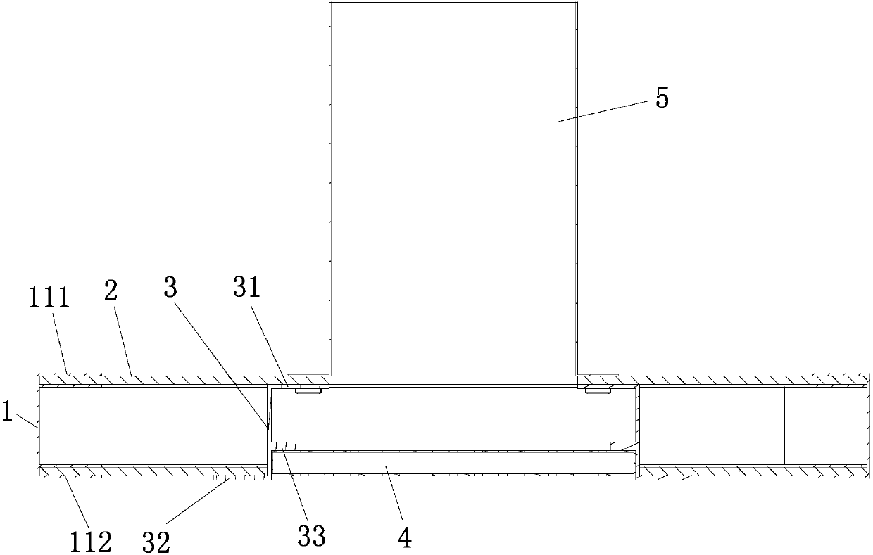
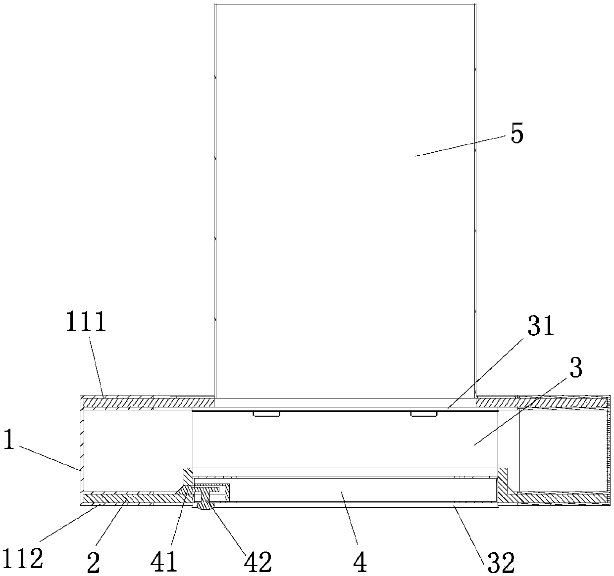
[0030] see Figure 1-6 , the new range hood includes a fume collection hood, the fume collection hood is composed of a side frame 1 and a panel 2, the panels 2 are at least two layers and arranged on the inner edge of the side frame 1 at intervals, the side frame The inner edge of the panel 1 is vertically arranged with installation positions for fixing the panel 2, and the middle part of the panel 2 constitutes the oil suction fume channel. The smoke collecting hood of the present invention is composed of a side frame 1 and upper and lower panels 2, which is different from the traditional structure formed by integral stretching and stamping of metal plates, which greatly reduces the mold cost. The side frame 1 and the panel 2. The material is changeable, such as metal, ceramic, glass, etc. can be used, and there are more processing methods and surface treatment methods. Compared with the traditional range hood, the range hood produced has a novel and unique appearance and a m...

no. 2 example

[0041] see Figure 7-8 , The difference between the present embodiment and the first embodiment of the new range hood is that the panel 2 has three upper, middle and lower layers. The insertion slot 11 assembled with the upper panel 1, the length of the upper slot body 111 protruding from the inner edge of the side frame 1 is greater than the length of the lower slot body 112 extending from the inner edge of the side frame 1; the insertion slot 11 assembled with the middle panel 1 , the length of the upper groove body 111 protruding from the inner edge of the side frame 1 is equal to the length of the lower groove body 112 extending from the inner edge of the side frame 1; the insertion groove 11 assembled with the lower panel 1, the upper groove body 111 extending out of the side frame The length of the inner edge of 1 is less than the length of the rain gutter body 112 protruding from the inner edge of the side frame 1, which can further save the cost of the side frame 1.

...

no. 3 example

[0044] see Figure 9 , The difference between this new range hood and the first embodiment is that the panel 2 is an arc-shaped panel, and the shape is further changed to meet the aesthetic requirements of more consumers.

[0045] Other unmentioned parts are the same as the first embodiment and will not be repeated.


PUM


Abstract

The invention discloses a novel extractor hood. The novel extractor hood comprises a smoke collecting hood, wherein the smoke collecting hood consists of side frames and panels, wherein at least two layers of panels are arranged on inner edges of the side frames in a mutually spaced mode; the inner edges of the side frames are vertically equipped with mounting positions used for panel fixing; andthe middle positions of the panels define an oil smoke absorbing channel. The extractor hood is co-defined by the side frames and the panels, and is different from a conventional structural form formed by integrally stretching and stamping a metal plate, so that the mould cost is greatly reduced; the side frames and the panels are various in material, and can select metal, ceramic, glass and the like, so that processing ways and surface treatment methods are more; and compared with a conventional extractor hood, the manufactured novel extractor hood has the advantages of being novel and uniquein appearance style, more high-end and elegant and capable of helping enterprises to develop the high-end market.

Description

technical field [0001] The invention relates to the field of range hoods, in particular to a novel range hood. Background technique [0002] National Patent Document No. CN105698238A discloses a range hood, which relates to the technical field of kitchen appliances. The range hood includes a fume collecting hood, and the fume collecting hood includes a fixed fume collecting hood and a movable fume collecting hood. [0003] In the prior art, the range hood, especially the top-suction type range hood, is formed by stretching and stamping a metal plate integrally. The cost of the mold is very high, and the manufactured range hood is homogeneous. Seriously, the high-end market cannot be opened. [0004] Therefore, further improvements are required. Contents of the invention [0005] The purpose of the present invention is to overcome the shortcomings of the above-mentioned prior art, and provide a new type of range hood, the panel of which is separately installed on the sid...

Claims


Application Information

Patent Timeline
IPC IPC(8): F24C15/20
Inventor 陈何燎
Owner 中山市百事特电器有限公司
Learn More