Three-dimensional three-mesh camera device and depth fusion method

A camera device and three-dimensional technology, applied in the field of image processing, can solve the problems of high computing resources, poor real-time performance and high real-time performance, and achieve the effect of high-quality three-dimensional images and excellent cost performance.

Active Publication Date: 2018-01-26
SHANGHAI ANVIZ TECH CO LTD
View PDF5 Cites 16 Cited by
  • Summary
  • Abstract
  • Description
  • Claims
  • Application Information

AI Technical Summary

Problems solved by technology

However, the intelligent analysis of 3D images is slightly lagging behind. For example, 3D photography, smart cars, human recognition and behavior analysis in mainstream applications have more research and less practical application. The reason is that there are all kinds of mainstream solutions at present. There are unsolvable defects, and it is impossible to form a high-quality solution. The defects of each plan are as follows:
[0004] 1. The structured light solution, under strong light, the laser speckle, the core technology of structured light, will be submerged, so it is not suitable for outdoors; at the same time, in terms of long-term monitoring, the laser emitting equipment is easy to break, and after replacing the equipment, it needs to be re-calibrated ;
[0005] 2. The binocular visible light parallax calculation scheme requires high computing resources to implement the algorithm, resulting in poor real-time performance, and the higher the resolution, the higher the accuracy required, the more complex the calculation. At the same time, the binocular scheme is subject to light and the texture of the object nature impact;
[0006] 3. TOF (Time of Flight) scheme, the resolution is low, but the detection angle is the widest, the real-time performance is high, no additional computing resources are required, and there is almost no algorithm development workload

Method used


Image

  • Three-dimensional three-mesh camera device and depth fusion method
  • Three-dimensional three-mesh camera device and depth fusion method
  • Three-dimensional three-mesh camera device and depth fusion method

Examples


Embodiment Construction

[0063] In order to make the above objects, features and advantages of the present invention more comprehensible, specific implementations of the present invention will be described in detail below in conjunction with the accompanying drawings.

[0064] In the following description, numerous specific details are set forth in order to provide a thorough understanding of the present invention. However, the present invention can be implemented in many other ways different from those described here, and those skilled in the art can make similar extensions without violating the connotation of the present invention, so the present invention is not limited by the specific implementations disclosed below.

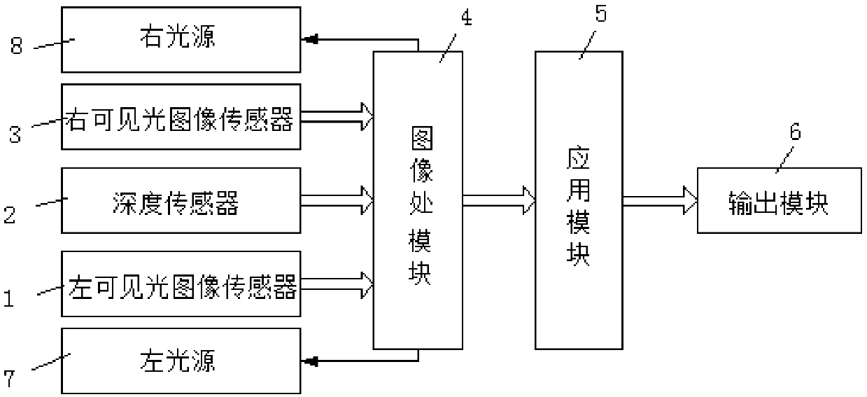
[0065] see figure 1 , in one embodiment, a three-dimensional trinocular imaging device includes: a left visible light image sensor 1 , a right visible light image sensor 3 , and a depth sensor 2 . The image processing module 4 can be realized by FPGA (Field-Programmable GateArray, ...


PUM


Abstract

The invention provides a three-dimensional three-mesh camera device and a depth fusion method. The device comprises left and right visible light image sensors used for collecting two left and right paths of visible light image data for a shooting object; a depth sensor used for collecting a path of depth image data for the shooting object, wherein in view of the shooting object, the pixel areas ofthe two left and right paths of visible light image data and the pixel area of the path of depth image data for the shooting object have a predetermined corresponding relation; and an image processing module connected with the left and right visible light image sensors and the depth sensor and used for performing depth fusion on the two left and right paths of visible light image data and the path of depth image data to obtain fused depth information of the pixel areas corresponding to the left path of visible light image data or right path of visible light image data, and thus a three-dimensional image can be determined according to the fused depth information, the left path of visible light image data or right path of visible light image data. High quality 3D images can be obtained.

Description

technical field [0001] The invention relates to the technical field of image processing, in particular to a three-dimensional trinocular camera device and a depth fusion method. Background technique [0002] At present, the two-dimensional (hereinafter referred to as 2D) imaging technology of cameras is becoming more and more mature, and high-definition, intelligent, and multi-dimensional will become the development trend of future cameras. At present, whether it is a chip manufacturer or an equipment manufacturer, the future development direction is aimed at two aspects of three-dimensional (hereinafter referred to as 3D) imaging and intelligent analysis, and has introduced a variety of solutions to solve some application problems. [0003] In terms of 3D imaging, there are three schemes of structured light, TOF and binocular visible light parallax to calculate depth, and some applications have been obtained in gesture recognition, 3D photography and industrial inspection. ...

Claims


Application Information

Patent Timeline
Patent Type & Authority Applications(China)
IPC IPC(8): H04N13/243H04N13/271H04N13/122
Inventor 周艇
Owner SHANGHAI ANVIZ TECH CO LTD
Why Eureka
Try Eureka