[0027] The specific embodiments of the present invention will be described in detail below with reference to the accompanying drawings. It should be understood that the specific embodiments described herein are only used to illustrate and explain the present invention, and not to limit the present invention.
[0028] In the present invention, if there is no explanation to the contrary, the positional words included in the term such as "one end, the other end", etc., only represent the position of the term under normal use, or are common names understood by those skilled in the art. It should not be seen as a limitation on the term.
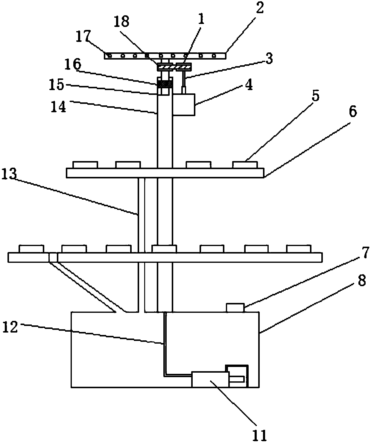
[0029] Such as figure 1 Shown: the present invention provides a new type of flowerpot, the new type of flowerpot includes a water pipe 14 arranged in a vertical direction, the lower end of the water pipe 14 is connected with a water tank 8, and the upper end of the water pipe 14 is connected with a sprinkler device, A water pump 11 is fixed in the water tank 8, and the outlet of the water pump 11 is communicated with the lower end of the water pipe 14 through a hose 12, and is located on the water pipe 14 between the nozzle device and the water tank 8. A plurality of potting frame mechanisms are also fixed from top to bottom. The water tank 8 here is filled with water for watering, and the water is delivered to the water pipe 14 through the water pump 11, and then sprayed from the sprinkler device, which can water the potted plants on the potting rack mechanism; the new flowerpot provided by the present invention can achieve For the purpose of watering multiple potted plants at the same time, using this device to replace the traditional manual watering not only effectively improves the watering efficiency, but also avoids water waste, which is suitable for wide application.
[0030] In a preferred embodiment of the present invention, in order to further improve the watering effect, the sprinkler device includes a sprinkler disc 2 and a support tube 15 communicating with the sprinkler disc 2, and one end of the support tube 15 is connected to the The spray head disc 2 is in communication, and the other end is movably connected to the upper end of the water pipe 14. The side wall of the spray head disc 2 communicates with a plurality of sprinkler heads 17, and the water enters the bracket pipe 15 through the water pipe 14 and then enters The spray head 17 sprays from the inside of the spray head disc 2.
[0031] In a preferred embodiment of the present invention, in order to increase the sprinkling range of the sprinkler head 17 and make the sprinkler irrigation more uniform, the sprinkler head device further includes a motor 4 fixed on the water pipe 14 and the support pipe 15 The lower end of the bracket at least partially extends into the water pipe 14, so that the bracket tube 15 can rotate on its own axis. The bracket tube 15 is also coaxially fixed with a first gear plate 18, and the rotor of the motor 4 A second chainring 1 is coaxially fixed on 3, and the first chainring 18 and the second chainring 1 are connected by a belt; the motor here can drive the second chainring through the second chainring 1 and the belt 18 rotates, so that the stent tube 15 can rotate on its own axis.
[0032] In a preferred embodiment of the present invention, in order to enable the support pipe 15 to rotate more smoothly, a bearing 16 is coaxially fixed in the water pipe 14, and the lower end of the support pipe 15 at least partially penetrates the bearing 16 , So that the support tube 15 can rotate on its own axis within the bearing 16.
[0033] In a preferred embodiment of the present invention, in order to enable the potted plant to be more stably fixed on the potted planter mechanism, the potted planter mechanism includes a bracket plate 6 fixed on the water pipe 14 and fixed on the The fixing ring 5 above the support plate 6 is used for engaging the potted plant, and the fixing ring 5 is fixed at the edge of the support plate 6.
[0034] In a preferred embodiment of the present invention, in order to collect excess irrigation water, the surface of the support plate 6 is recessed downward to form a groove structure, and the fixing ring 5 is fixed in the groove structure. The potted plant frame mechanism also includes a return pipe 13, one end of the return pipe 13 is connected to the groove structure, and the other end is connected to the water tank 8. The excess irrigation is used to collect in the groove structure and pass through The return pipe 13 returns to the water tank 8 to complete the recycling of the irrigation water.
[0035] In a preferred embodiment of the present invention, in order to make the potted plants on the support tray 6 be evenly irrigated and watered, the support tray 6 has a cylindrical structure, and the water pipe 14 penetrates the center of the support tray 6 , So that the support plate 6 and the water pipe 14 are coaxially arranged.
[0036] In a preferred embodiment of the present invention, in order to improve the utilization rate of the novel flowerpot, the number of the potting rack mechanisms is greater than two groups.
[0037] In a preferred embodiment of the present invention, in order to improve the irrigation effect, the diameter of the support disk 6 in the plurality of potting mechanisms increases from top to bottom, and the fixing ring 5 is distributed around the support disk 6 here. Edge, so that the upper support tray 6 cannot cover the potted plants on the lower support tray.
[0038] In a preferred embodiment of the present invention, in order to facilitate the filling of the water tank 8, a water inlet pipe 7 is connected to the water tank 8.
[0039] The preferred embodiments of the present invention are described in detail above with reference to the accompanying drawings. However, the present invention is not limited to the specific details in the above embodiments. Within the scope of the technical concept of the present invention, many simple modifications can be made to the technical solutions of the present invention. These simple modifications all belong to the protection scope of the present invention.
[0040] In addition, it should be noted that the various specific technical features described in the above-mentioned specific embodiments can be combined in any suitable manner without contradiction. In order to avoid unnecessary repetition, the present invention is The combination method will not be explained separately.
[0041] In addition, various different embodiments of the present invention can also be combined arbitrarily, as long as they do not violate the idea of the present invention, they should also be regarded as the content disclosed in the present invention.