
Knapsack type air atomizing sprayer

An air atomization and sprayer technology, which is applied in the direction of spraying devices, liquid spraying devices, etc., can solve the problems of narrow use range, low use efficiency, waste of liquid medicine, etc., achieve good atomization effect, good use effect, and reduce labor Effect

Pending Publication Date: 2018-01-30
广西裕阳科技有限公司
View PDF10 Cites 0 Cited by
  • Summary
  • Abstract
  • Description
  • Claims
  • Application Information

AI Technical Summary

Problems solved by technology

[0002] Sprayer is the abbreviation of spray equipment. A sprayer is a device that uses air suction to turn liquid medicine or other liquid medicine into mist and sprays it evenly on other objects. The existing sprayer has a single structure and a narrow range of use. Different types of sprayers only Can be used for specialized operations, and the efficiency is not high
In addition, some of the existing traditional sprayers are powered by manual manual or battery-driven diaphragm pumps. The failure rate of traditional sprayers is high, which affects the efficiency of spraying. Moreover, the range of traditional sprayers is relatively short, generally about 3 meters. , the coverage of the liquid medicine is small, the work efficiency is low, and the liquid medicine is wasted. It cannot achieve the effect of complete spraying on tall fruit trees, and the spraying effect on hidden places is not good.
Although the vehicle-mounted sprayer can have a better spraying effect, it is bulky, heavy, inconvenient to use, not conducive to the use in hilly and mountainous areas, and the cost is high, so it is not suitable for farmers

Method used


Image

  • Knapsack type air atomizing sprayer
  • Knapsack type air atomizing sprayer
  • Knapsack type air atomizing sprayer

Examples


Embodiment Construction

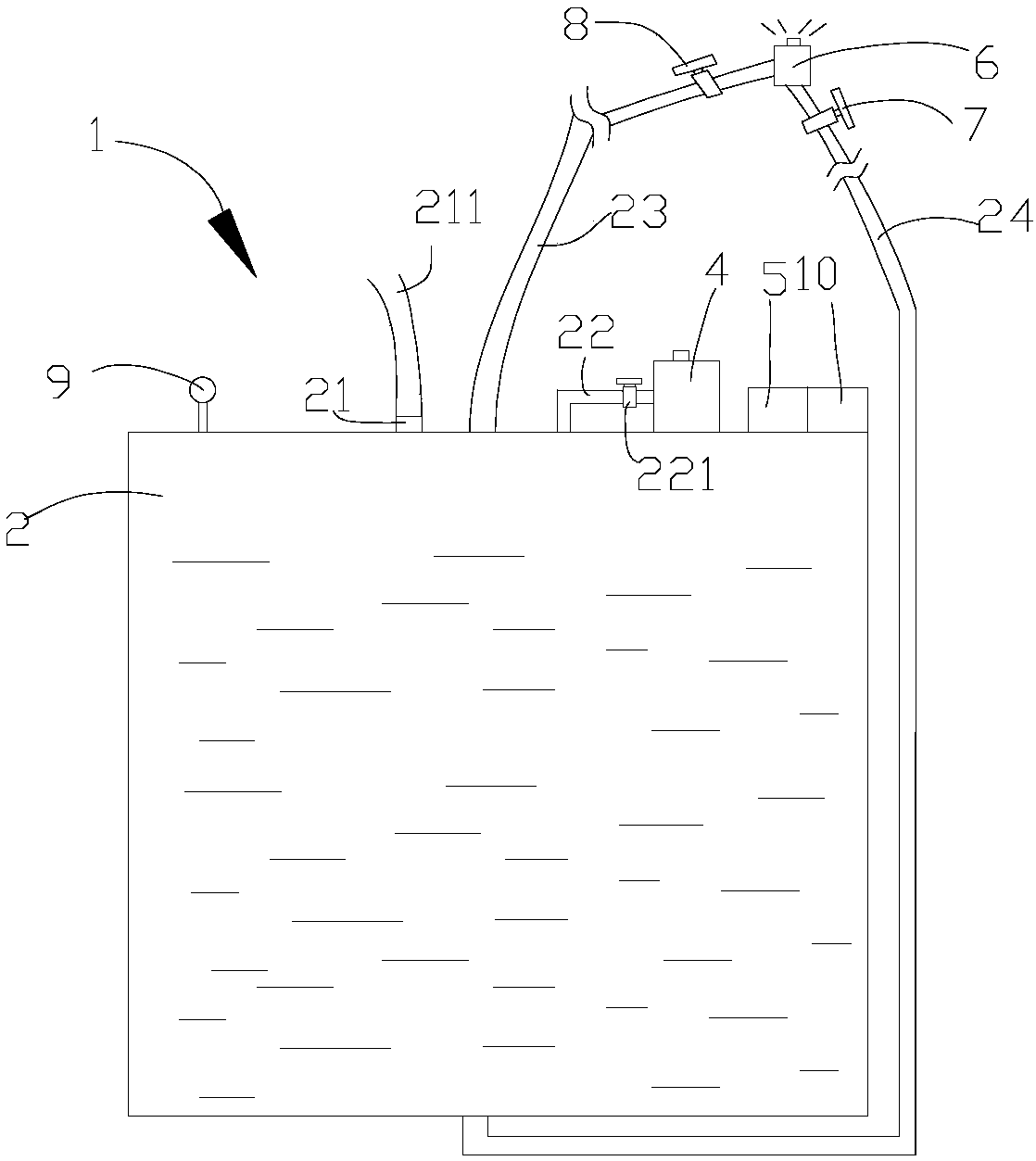
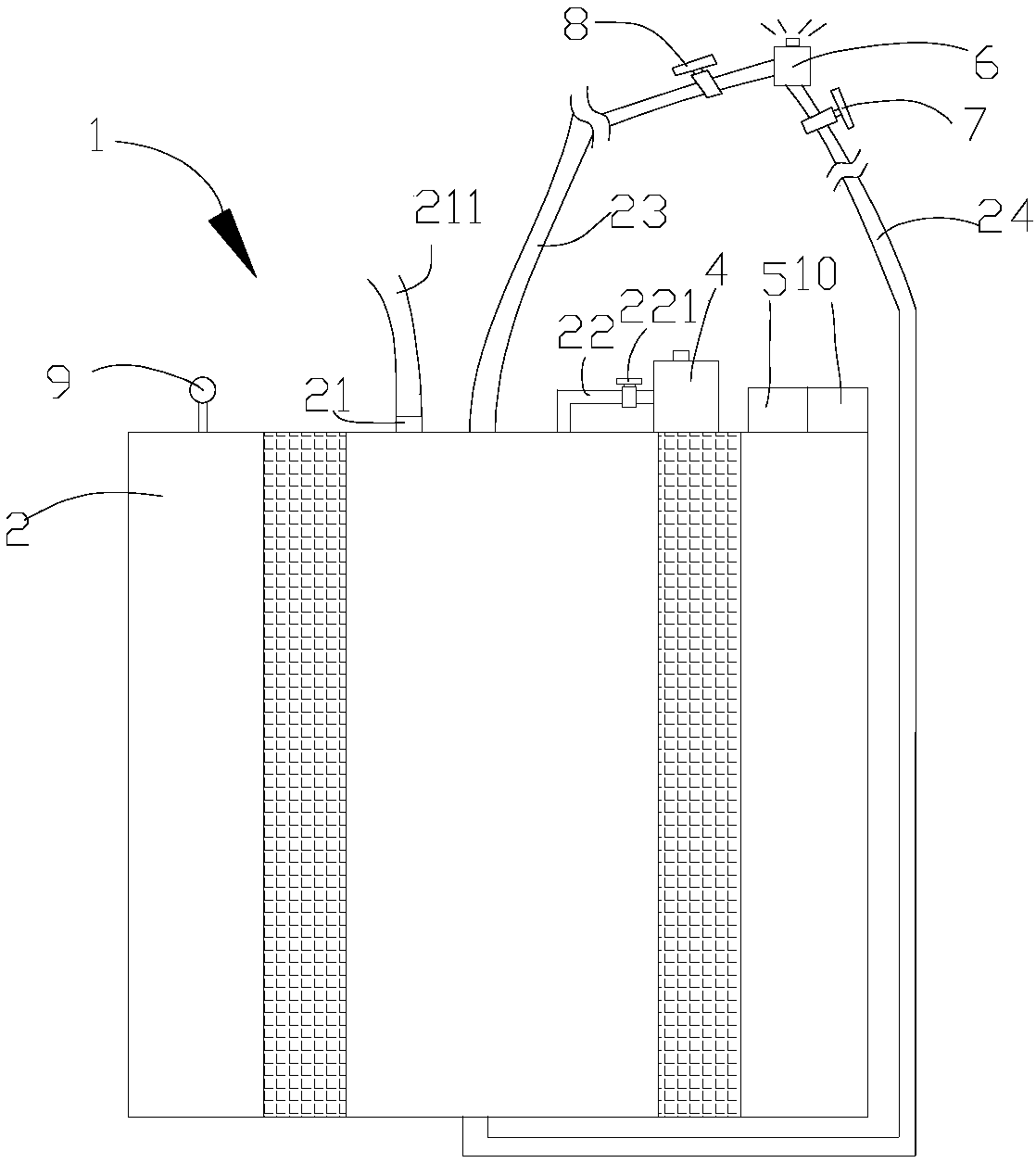
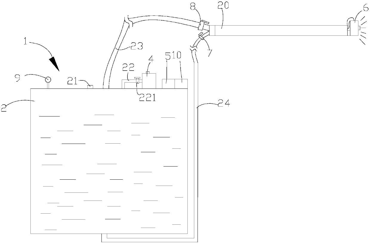
[0028] see figure 1 and figure 2 , in a preferred embodiment of the present invention, a knapsack air atomization sprayer 1 includes an air-liquid tank 2, a shoulder strap 3, an air source device 4, a power unit 5 and an air-liquid atomization nozzle 6. A double-shoulder strap 3 is installed on the rear side of the gas-liquid tank 2, which is convenient for the operator to carry the sprayer 1 on his back. The upper part of the gas-liquid tank 2 is provided with a liquid inlet 21 for introducing liquid medicine into the gas-liquid tank 2, and the liquid inlet 21 is provided with a sealing cover or a sealing plug for sealing the liquid inlet 21. When the operator removes the sealing cover or the sealing plug from the liquid inlet 21, the external medicinal liquid can be introduced into the gas-liquid tank 2 through the liquid inlet 21. After the introduction is completed, the The sealing cover or the sealing plug seals the liquid inlet 21, that is, the work of adding liquid ...


PUM


Abstract

The invention relates to the field of sprayers, and in particular to a knapsack type air atomizing sprayer, which comprises an air-liquid tank, two shoulder straps, an air source device, a power device, and an air-liquid atomizing spray head. The double shoulder straps are arranged on the rear side surfaces of the air-liquid tank. A liquid inlet is formed in the upper part of the air-liquid tank;a sealing cap or a sealing plug is arranged at the liquid inlet. An air inlet pipe and an air outlet pipe are connected with the upper part of the air-liquid tank, are communicated with the internal part of the air-liquid tank, and are arranged above a medicine liquid, wherein a check valve is installed on the air inlet pipe, and one end of the air inlet pipe away from the air-liquid tank is connected with the air source device, the air source device is connected with the power device, the air source device and the power device are jointly installed on the air-liquid tank, one end of the air outlet pipe away from the air-liquid tank is connected with the air inlet end of the gas-liquid atomizing nozzle. The liquid inlet end of the gas-liquid atomizing nozzle is connected with the air-liquid tank through a liquid outlet pipe, and the end of the liquid outlet pipe connected with the air-liquid tank is located at the lower part of the air-liquid tank. The sprayer has the advantages that it saves the medicine and has good spraying effect.

Description

technical field [0001] The invention relates to the field of sprayers, in particular to a knapsack air atomization sprayer. Background technique [0002] Sprayer is the abbreviation of spray equipment. A sprayer is a device that uses air suction to turn liquid medicine or other liquid medicine into mist and sprays it evenly on other objects. The existing sprayer has a single structure and a narrow range of use. Different types of sprayers only It can be used for special operations, and the use efficiency is not high. In addition, some of the existing traditional sprayers are sprayers powered by manual hand crank or battery-driven diaphragm pump. The failure rate of traditional sprayers is high, which affects the efficiency of spraying. Moreover, the range of traditional sprayers is relatively short, generally about 3 meters , the coverage area of ​​medicinal liquid is little, and work efficiency is low, waste medicinal liquid, can not reach the effect of spraying medicine f...

Claims


Application Information

Patent Timeline
Patent Type & Authority Applications(China)
IPC IPC(8): B05B9/08
Inventor 蒙日灿
Owner 广西裕阳科技有限公司
Learn More