
Travelling mechanism of track inspection robot

A technology for inspection robots and walking mechanisms, applied in the directions of manipulators, manufacturing tools, etc., can solve the problems of difficult turning and climbing, difficult precise positioning, and high rack cost, achieve precise positioning, achieve positioning, and meet the needs of small radius turns Effect

Pending Publication Date: 2018-01-30
SHENZHEN LAUNCH DIGITAL TECH
View PDF7 Cites 37 Cited by
  • Summary
  • Abstract
  • Description
  • Claims
  • Application Information

AI Technical Summary

Problems solved by technology

[0003] The friction method is used because it relies on wheel friction, and it is difficult to achieve precise positioning due to slippage
However, the form of rack and pinion will not slip, but it is not easy to turn and climb, and the cost of the rack is relatively high

Method used


Image

  • Travelling mechanism of track inspection robot
  • Travelling mechanism of track inspection robot
  • Travelling mechanism of track inspection robot

Examples


Embodiment Construction

[0023] The present invention will be further described below in conjunction with accompanying drawing:

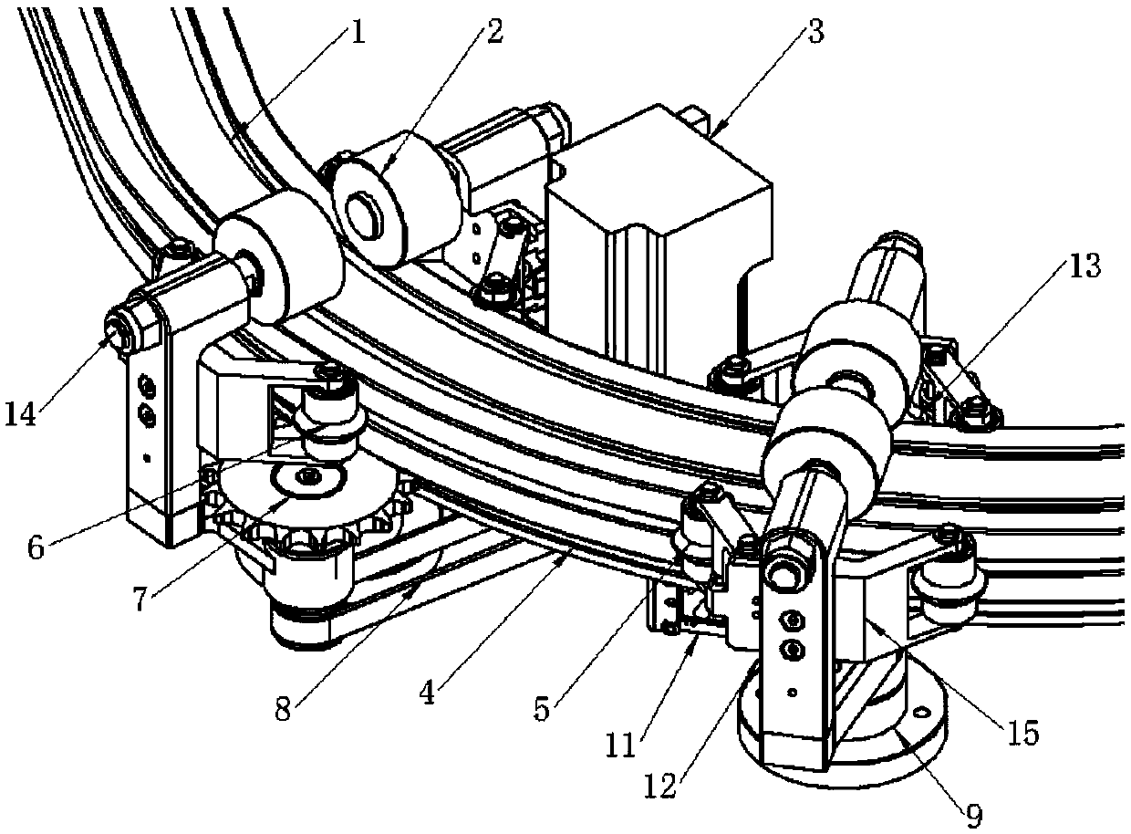
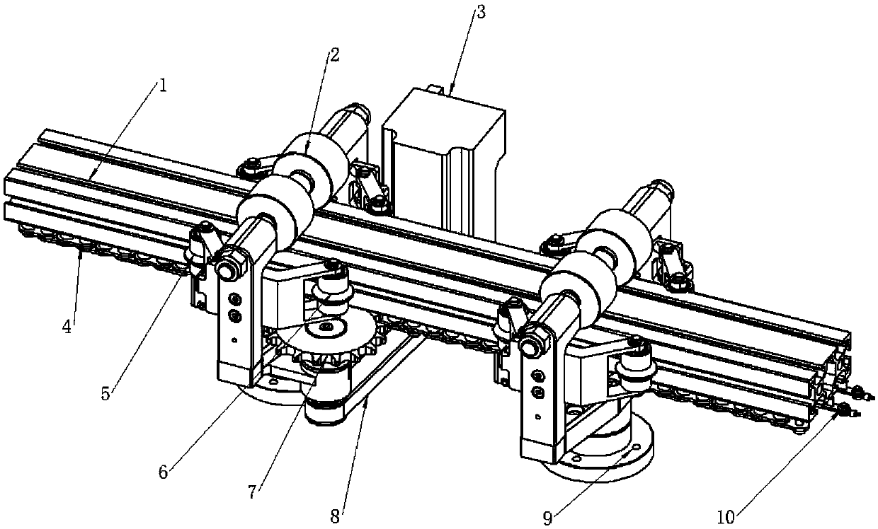
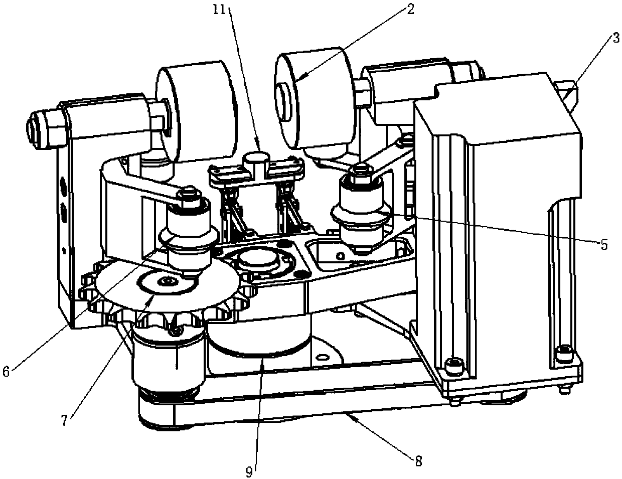
[0024] Such as figure 1 , figure 2 and image 3 As shown, a track inspection robot walking mechanism of the present invention includes a track, a drive mechanism and a power supply device, the drive mechanism moves along the track, and the inspection robot is installed on the drive mechanism;

[0025] The track includes an aluminum profile 1 and a chain 4, and the chain 4 is arranged below the aluminum profile 1 in parallel and is fixedly connected to the lower side of the aluminum profile 1;

[0026] The driving mechanism includes a suspension arm 12, a crossbeam, a stable wheel set, a sprocket 7, a drive motor 3 and a steering device 9. Two suspension arms 12 and the crossbeam form a U-shaped structure, and the aluminum profile 1 is located in the U-shaped structure, and the suspension arm 12 The stable wheel set is in sliding contact with the aluminum profile 1, the ...


PUM


Abstract

The invention discloses a travelling mechanism of a track inspection robot. The travelling mechanism comprises a track and a driving mechanism, the driving mechanism moves along the track, and the inspection robot is installed on the driving mechanism; the track comprises an aluminum profile and a chain which is arranged under the aluminum profile in parallel; the driving mechanism comprises suspension arms, a cross beam, a steady wheel set, a chain wheel, a driving motor and a steering device, a U-shaped structure is formed by the two suspension arms and the cross beam, the suspension arms make slideable contact with the aluminum profile through the steady wheel set, the chain wheel is horizontally arranged and rotationally connected with the cross beam, the chain wheel meshes with the chain, a torque input shaft of the chain is fixedly connected with a torque output shaft of the driving motor through a transmission belt, and the driving motor is fixedly connected with the cross beam.In the travelling mechanism, the standard industrial aluminum profile is used as the track, the chain is used as a path, the chain wheel is used as a driving wheel, and a chain-drive mode is adoptedso that precise positioning can be achieved, and turning and climbing can be easily achieved; the steering shaft is adopted as a steering knuckle so that the requirements for small-radius turning canbe met.

Description

technical field [0001] The invention relates to a robot walking mechanism, in particular to a track inspection robot walking mechanism. Background technique [0002] At present, robots are used more and more widely. In the occasions that have certain requirements for safety, more and more robots that walk along the track are used. Most of the currently used tracks follow the I-shaped track of the self-propelled conveying robot. There is a situation that the weight is large, the price is high, and it is difficult to realize a small radius turning. In places where equipment is dense, such as power rooms, it is difficult to meet actual needs. Therefore, it is necessary to develop a robot with low price, reliable walking and small turning radius. The prior art mainly advances by the self-friction of the driving wheel, or by the racks laid on the track, and advances through the meshing of the gears. [0003] The friction form is adopted because it relies on wheel friction, a...

Claims


Application Information

Patent Timeline
IPC IPC(8): B25J5/02
Inventor 席文兵任春勇鲜开义周仁彬
Owner SHENZHEN LAUNCH DIGITAL TECH
Learn More