Information controller switching device

A switching device and controller technology, which is applied in general control systems, control/regulation systems, instruments, etc., can solve the problems of low real-time performance of active/standby switching, complicated external circuit design, and inability to strictly guarantee non-disruptive switching.

Inactive Publication Date: 2018-01-30
天津赛因哲信息技术有限公司
View PDF0 Cites 0 Cited by
  • Summary
  • Abstract
  • Description
  • Claims
  • Application Information

AI Technical Summary

Problems solved by technology

[0002] Among the existing controller redundancy switching technologies, there are three implementation methods that are widely used: 1) Multiplex the Ethernet channel between the active and standby controllers and the monitoring system (HMI) to exchange redundant information. The configuration is relatively simple, but the real-time performance of the active / standby switchover is low. Due to the shared network with the HMI, only a small amount of information can be exchanged between the active and standby machines, and the undisturbed switchover cannot be strictly guaranteed; 2) Use a dedicated redundant communication channel (such as HDLC, 100M Ethernet, etc.), taking into account the switching and synchronization functions at the same time, the real-time performance of the active-standby switching is low, and it cannot guarantee the non-disruptive switching in the case of fast logic tasks. On the other hand, when the redundant communication channel fails , the system will have dual-master controllers, which will have a fatal impact on system operation; 3) Use a dedicated master-standby switching circuit, such as a synchronous interlock circuit based on FPGA design, etc. The external circuit design is more complicated and the failure rate is higher

Method used


Image

  • Information controller switching device

Examples


Embodiment Construction

[0009] In order to make the technical means, creative features, objectives and effects of the present invention easy to understand, the present invention will be further explained below in conjunction with specific embodiments.

[0010] Example:

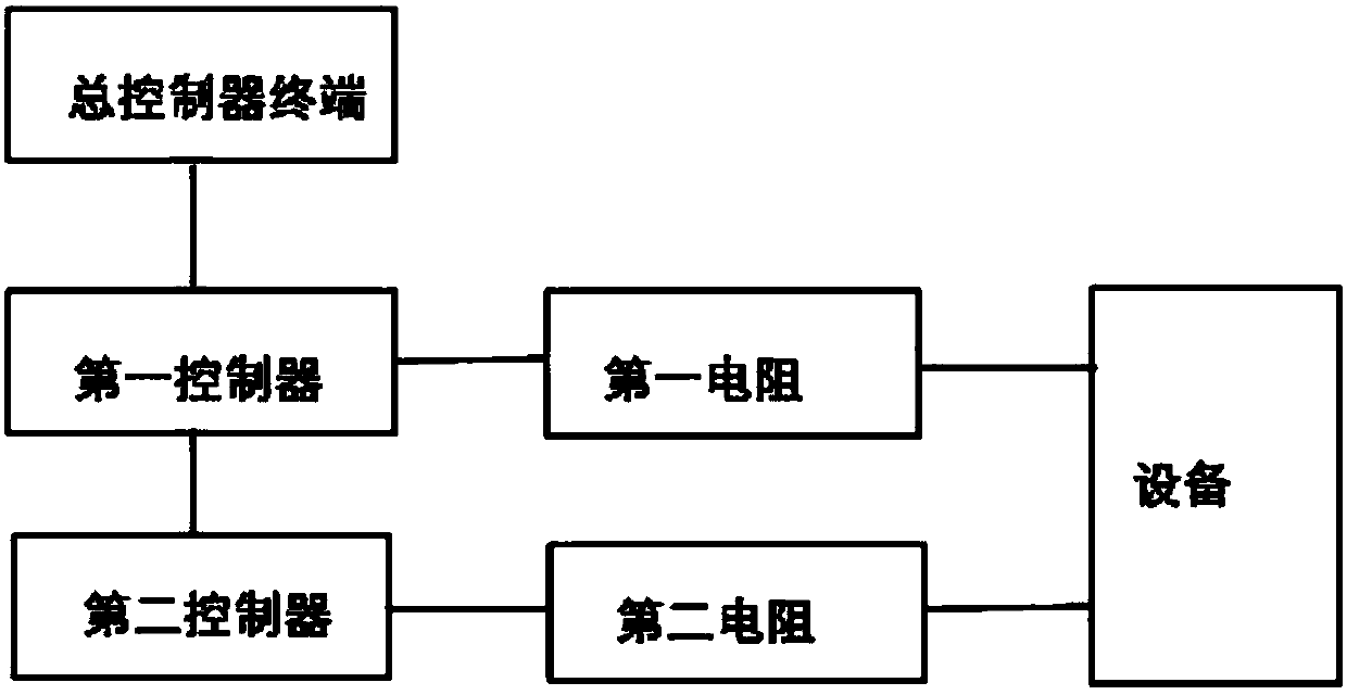
[0011] Such as figure 1 As shown, an information controller switching device includes a master controller terminal, the master controller is connected to a first controller by a control line; the master controller is connected to a second controller by a control line; the first control One end of the device is connected to the first resistor by a control line; one end of the second controller is connected to a second resistor by a control line; one end of the first resistor is connected to the transmitting device by a control line; One end is connected to the transmitting device by a control line.

[0012] Among them, the other end of the main controller terminal performs data communication through a dedicated Ethernet to realize the inte...


PUM


Abstract

The present invention belongs to the field of information, and in particular relates to an information controller switching device. The device comprises a main controller terminal being connected witha first controller through a control line; the main controller is connected with a second controller through a control line; one end of the first controller is connected with a first resistor througha control line; one end of the second controller is connected with a second resistor through a control line; one end of the first resistor is connected with a transmitting device through a control line; one end of the second resistor is connected with the transmitting device through a control line, so that the switching time of a host can reach a hundred microseconds when a fault occurs, and requirement of a redundant system with very high control precision can be met and multiple control of a terminal is realized.

Description

【Technical Field】 [0001] The invention relates to an information device, in particular to an information controller switching device. 【Background technique】 [0002] In the existing controller redundancy switching technology, there are three implementation methods that are widely used: 1) Multiplexing the Ethernet channel between the active and standby controllers and the monitoring system (HMI) to exchange redundant information. This method is networked and The configuration is relatively simple, but the real-time performance of the active / standby switch is low. Due to the shared network with the HMI, only a small amount of information can be exchanged between the active and standby computers, and the undisturbed switch cannot be strictly guaranteed; 2) Use dedicated redundant communication channels (such as HDLC, Fast Ethernet, etc.), while taking into account the switching and synchronization functions. This method has low real-time performance of active and standby switching,...

Claims


Application Information

Patent Timeline
Patent Type & Authority Applications(China)
IPC IPC(8): G05B9/03
Inventor 杨晓强
Owner 天津赛因哲信息技术有限公司
Why Eureka
Try Eureka