Starting method of 3-phase induction motor and decanter type centrifugal separator

A technology of induction motor and centrifugal separation, which is applied to the starter, motor generator/starter, centrifuge and other directions of a single multi-phase induction motor, which can solve the problems of malfunction, cost increase, and mixing with electrical equipment, etc., and achieve reduction The effect of increasing magnitude

Inactive Publication Date: 2018-01-30
TOMOE ENGINEERING CO LTD
View PDF7 Cites 2 Cited by
  • Summary
  • Abstract
  • Description
  • Claims
  • Application Information

AI Technical Summary

Problems solved by technology

[0003] The drum is a large machine with a large moment of inertia. Therefore, the size of the three-phase induction motor and the inverter for starting become larger, resulting in an increase

Method used


Image

  • Starting method of 3-phase induction motor and decanter type centrifugal separator
  • Starting method of 3-phase induction motor and decanter type centrifugal separator
  • Starting method of 3-phase induction motor and decanter type centrifugal separator

Examples


Embodiment Construction

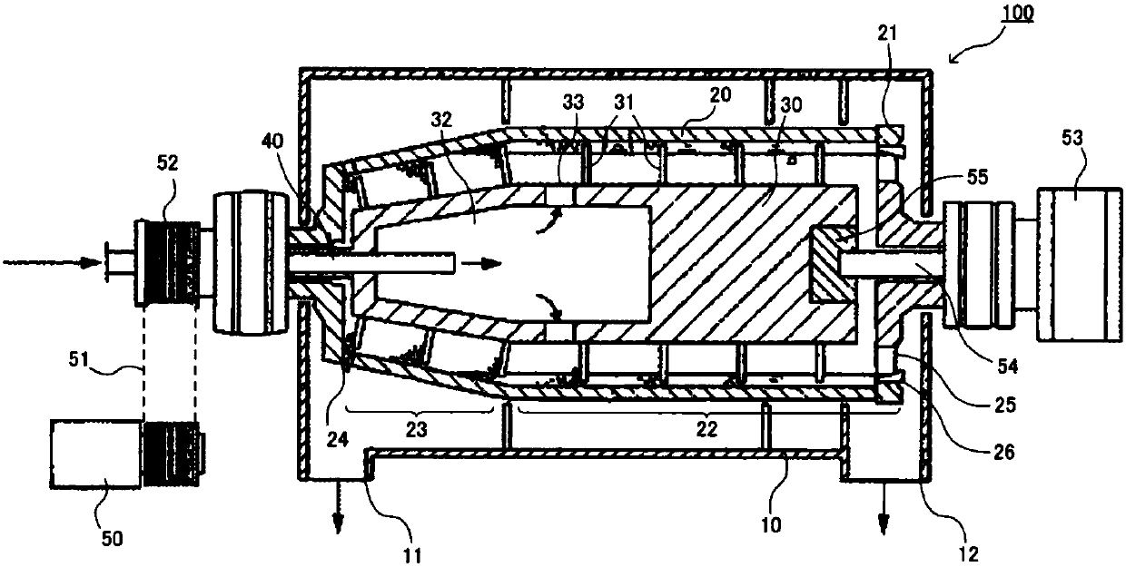
[0039] figure 1 It is a schematic cross-sectional view of a horizontal decanter centrifuge (corresponding to a decanter centrifugal separation device). However, the invention of the present application can also be applied to a vertical decanter centrifuge. The decanter centrifuge 100 includes: a housing 10; a drum 20 accommodated inside the housing 10; a screw conveyor 30 disposed inside the drum 20; a supply nozzle 40 used for feeding solids containing the liquid to be treated; and a driving device 50 which rotates the drum 20 .

[0040] In the lower portion of the housing 10 , a heavy fraction outlet 11 is formed on one end side of the drum 20 in the direction of the rotation axis, and a light fraction outlet 12 is formed on the other end side. Power generated by the driving device 50 is transmitted to the pulley 52 via the rotating belt 51 , and the rotating drum 20 is rotated by the rotation of the pulley 52 . In addition, power is transmitted to the screw conveyor 30 v...


PUM


Abstract

The invention provides a starting method of a 3-phase induction motor. Compared with a basic starting method, the starting method is advantaged in that the temperature increase amplitude of the 3-phase induction motor during the starting process of a decanter type centrifuge can be reduced. By means of the starting method of the 3-phase induction motor, a revolving drum of a decanter type centrifugal separator carrying out centrifugal separation on an object to be processed rotates faster from a stop state to a target speed. The starting method is characterized in that by employing a star connection mode, a power supply is electrically connected with the 3-phase induction motor, a thyristor is employed to shear waveform of voltage supplied from the power supply to the 3-phase induction motor while the 3-phase induction motor is started, furthermore, when the current effective value of the 3-phase induction motor is reduced in the starting process, a process for increasing the conduction angle of the thyristor is carried out.

Description

technical field [0001] The present invention relates to a method for starting a three-phase induction motor that accelerates the rotation of a bowl of a decanter that centrifuges a processed product from a stopped state to a target speed. Background technique [0002] A decanter centrifuge is known as a centrifugal separation device for solid-liquid separation. This decanter centrifuge is used for dehydration treatment of various synthetic resins such as polyvinyl chloride resin (PVC), polyethylene, polystyrene, and polypropylene. Generally, such a decanter centrifuge has: a drum that applies a centrifugal force to the processed material to separate the solid from the liquid; a screw conveyor that transports the solid material after the solid-liquid separation toward the discharge port; a three-phase induction motor that It is used to drive the drum to rotate it; and an inverter device for inverter control of the three-phase induction motor. [0003] The drum is a large ma...

Claims


Application Information

Patent Timeline
IPC IPC(8): H02P1/32B04B9/04
CPCB04B9/10
Inventor 冈安祐次
Owner TOMOE ENGINEERING CO LTD
Why Eureka
Try Eureka