Staggered-distance extrusion forming device and method for bending component

A technology of extrusion forming and staggering, applied in the direction of metal extrusion dies, etc., can solve the problems of difficult manufacturing process, difficulty in quality assurance, poor flexibility, etc., and achieve the effect of rich variety, diversified application fields, and good shaping performance

Active Publication Date: 2018-02-02
福建祥鑫股份有限公司
View PDF11 Cites 5 Cited by
  • Summary
  • Abstract
  • Description
  • Claims
  • Application Information

AI Technical Summary

Problems solved by technology

[0008] The purpose of the present invention is to provide a bending member staggered extrusion forming method to solve a series of bottleneck

Method used


Image

  • Staggered-distance extrusion forming device and method for bending component
  • Staggered-distance extrusion forming device and method for bending component
  • Staggered-distance extrusion forming device and method for bending component

Examples


specific Embodiment approach 1

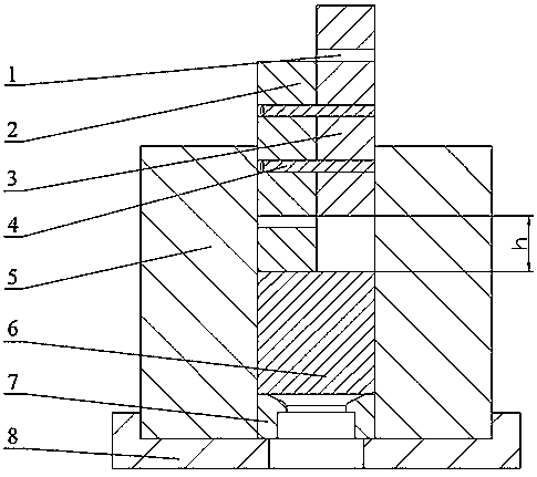
[0037] Specific implementation mode one: combine Figure 1~Figure 3This embodiment will be described. In this embodiment, the punch is designed as a left-right symmetrical two-part structure. This embodiment includes: a positioning hole 1 , a left punch 2 , a right punch 3 , a positioning pin 4 , an extrusion barrel 5 , a blank 6 , a mandrel 7 and a base 8 . This embodiment is completed by the following steps: 1. Make the punch into two parts, the left punch 2 and the right punch 3; 2. Stagger the left punch 2 and the right punch 3 according to the curvature of the required bending member. The distance h is placed, and the positioning pin 4 is inserted into the positioning hole 1 between the two punches to fix it; 3. Fix the base 8 on the press workbench; 4. Place the extrusion cylinder 5 above the base 8; 5. 1. Put the mandrel 7, the blank 6, the combination of the left punch 2 fixed with the positioning pin 4 and the right punch 3 in the extrusion cylinder 5 in turn; six, l...

specific Embodiment approach 2

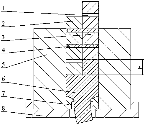
[0038] Specific implementation mode two: combination Figure 4~Figure 6 Describe this embodiment. The punch in this embodiment is designed as a three-part structure. This embodiment includes: positioning hole 1, left punch 2, right punch 3, positioning pin 4, extrusion barrel 5, blank 6, and mandrel 7 And base 8, middle punch 9. This embodiment is completed by the following steps: 1. Set the left punch 2, the middle punch 9 and the right punch 3 at staggered distances according to the curvature of the required bending parts, and the adjacent punches are staggered by a certain distance h / 2. Fix it with positioning pin 4; 2. Fix the base 8 on the press table; 3. Place the extrusion cylinder 5 above the base 8; 4. Put the core mold 7 into the extrusion cylinder 5 in sequence , blank 6, the combination of left punch 2, middle punch 9 and right punch 3 fixed by positioning pin 4; five, the combined punch is loaded, left punch 2, middle punch 9 and right punch The head 3 contacts...

specific Embodiment approach 3

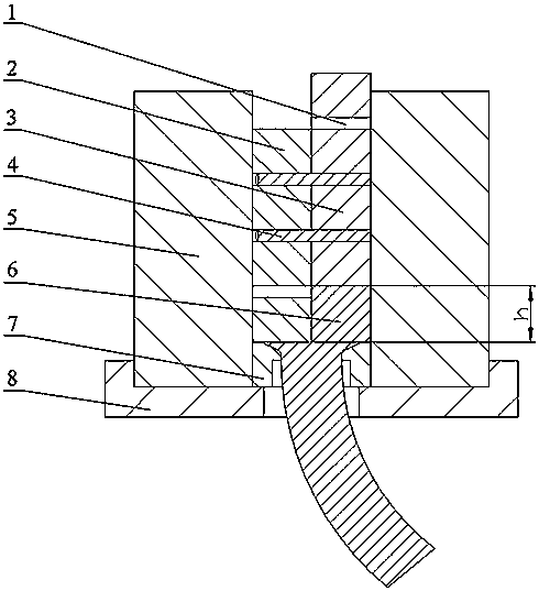
[0039] Specific implementation mode three: combination Figure 7~Figure 9 Describe this embodiment. The punch in this embodiment is designed as a three-part structure. This embodiment includes: positioning hole 1, left punch 2, right punch 3, positioning pin 4, extrusion barrel 5, blank 6, and mandrel 7 And base 8, middle punch 9. Wherein, the stagger amount between the left punch 2 and the middle punch 9 is h / 2. Other connection relationships are the same as those in the second embodiment.


PUM


Abstract

The invention discloses a staggered-distance extrusion forming device and method for a bending component, and relates to a extrusion forming device and method for the bending component. The device andthe method aim to solve a series of problems that in a traditional bending component manufacturing process, the number of required procedures is large, the flexibility of the component is poor, the production efficiency is low, and quality control is difficult to achieve. According to the method, a conventional integral punch for extruding is divided into two or more than two split structures; the split punches are arranged in a staggered manner according to a certain relative displacement amount and fixed; then integral loading forming of blanks is carried out; and the curvature change of the bending component subjected to extrusion forming can be regulated. The single shape feature that conventional extrusion products are mostly long straight lines is broken through, the variety range of the products capable of being formed is enriched, and the application field also tends to be diversified. According to the method, the double effects that extruding and bend and forming are integrated are achieved in a single-pass extrusion technology process, additional procedures are not needed, the required bending component can be machined at one time, the machining process is shortened, theproduction efficiency is improved, and the manufacturing cost is reduced. The staggered-distance extrusion forming device and method for the bending component is used for extrusion and machining forming of the bending component.

Description

technical field [0001] The invention relates to a metal extrusion forming method, in particular to a bending member offset extrusion forming method, and belongs to the technical field of bending member extrusion forming. Background technique [0002] Bending is a plastic processing method that bends blanks or semi-finished products such as plates, pipes, profiles, etc., into components with a certain angle or a certain shape with molds or other tools. It can achieve lightweight manufacturing effect and can meet various practical needs of structural parts with curvature in different shapes. Therefore, it is widely favored by aerospace, automobile, shipbuilding and other fields, and it is a green manufacturing technology. [0003] At present, there are many processes for component bending, mainly including: press bending, roll bending, push bending, numerical control bending, local heating bending and laser bending, etc., but the process principles and characteristics of vario...

Claims


Application Information

Patent Timeline
IPC IPC(8): B21C23/21B21C25/02
CPCB21C23/21B21C25/02
Inventor 李峰李续博刘阳
Owner 福建祥鑫股份有限公司
Why Eureka
Try Eureka