
Sewing machine for long-striped ribbon

A technology for ribbons and sewing machines, applied to sewing machine components, sewing equipment, cloth feeding mechanisms, etc., can solve problems such as reduced productivity, poor sewing efficiency, and easily damaged fabrics

Active Publication Date: 2018-02-02
YAMATO SEWING MASCH MFG CO LTD
View PDF7 Cites 3 Cited by
  • Summary
  • Abstract
  • Description
  • Claims
  • Application Information

AI Technical Summary

Problems solved by technology

[0004] However, in this case, there is a problem that in order to cut the sewn strips, manual work with scissors or the like is required, and the sewing work must be temporarily interrupted every time, so the efficiency of the sewing work tends to deteriorate and the productivity decreases. , and production costs increase, and the use of scissors, etc. is also easy to damage the fabric

Method used


Image

  • Sewing machine for long-striped ribbon
  • Sewing machine for long-striped ribbon
  • Sewing machine for long-striped ribbon

Examples


Embodiment Construction

[0056] Hereinafter, embodiments of the present invention will be described based on the drawings.

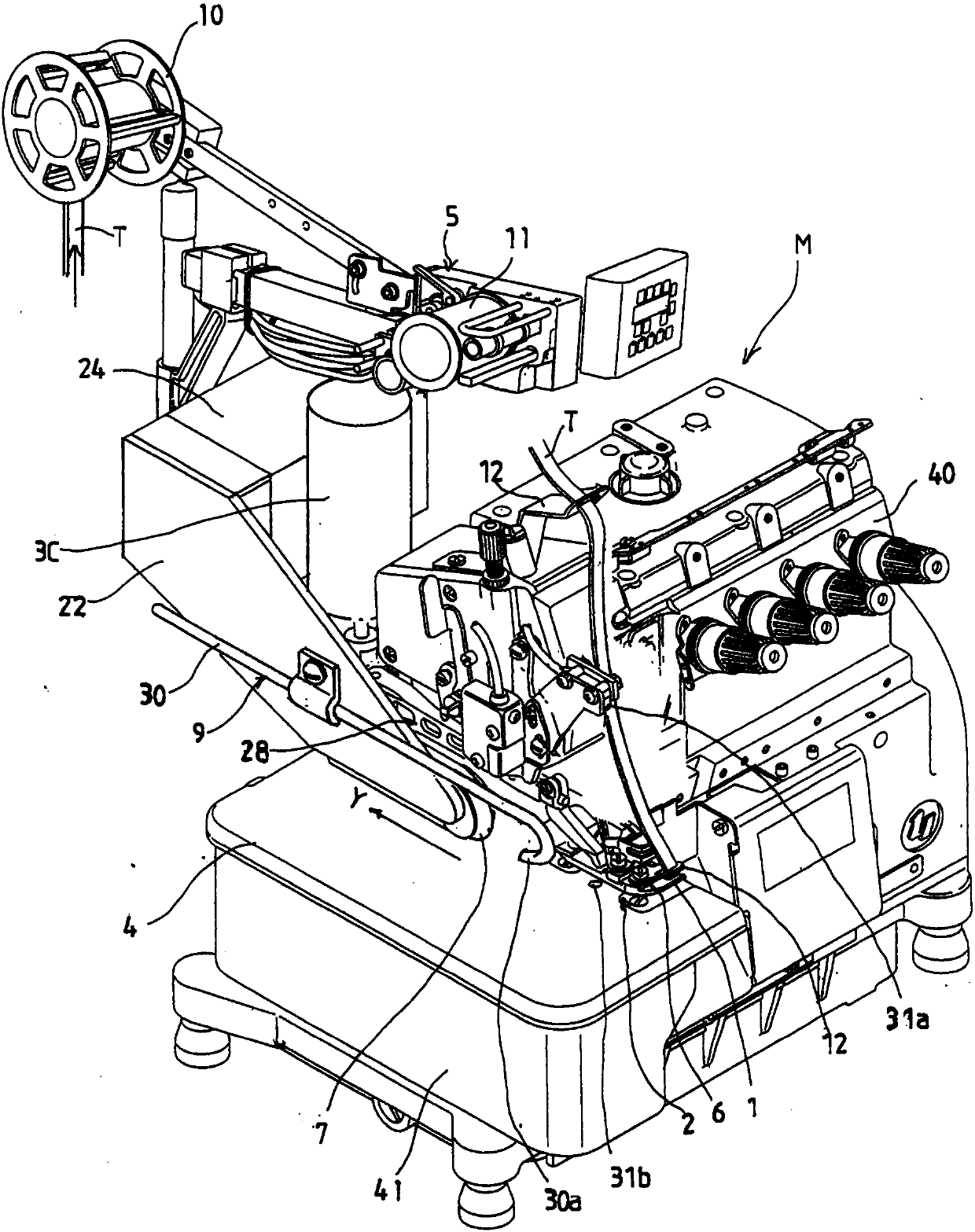
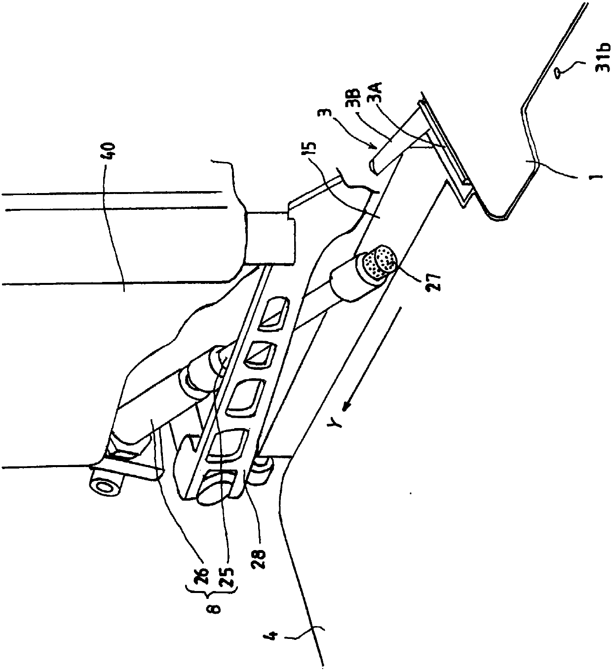
[0057] figure 1 It is an overall perspective view of a sewing machine for sewing long strips according to the present invention, figure 2 It is an enlarged perspective view of the main part of the sewing machine for sewing long ribbons.

[0058] In the above-mentioned sewing machine M for sewing long strips, the upper part of the sewing machine base part 41 connected to the left side part of the sewing machine frame 40 is provided with a Figure 7 The shown special shape cuts the material W and the needle plate 1 and the material slide plate (cross plate) 4 that guide the conveyance of the cut material W to the sewing travel direction Y, and the above-mentioned The feed dog and its drive mechanism for intermittently feeding the cut material W toward the sewing travel direction Y are well known, and therefore illustrations and descriptions of specific structures are omitted. ...


PUM


Abstract

The present invention provides a sewing machine for sewing a tape, which has a fabric blocking device, a fabric blocking device that sequentially transports and feeds a plurality of fabrics while theside sequentially transports a plurality of fabrics, and the fabric is continuously fed and fed by the sewing portion on the side edges of the plurality of fabrics. In the case where the sewing fabricterminating end portion of the preceding fabric reaches the predetermined tape cutting position, the fabric portion that protrudes toward the downstream side in the sewing proceeding direction of thetape sewn portion in the sewing start end portion of the succeeding fabric can be partially avoided. With the tape cutting position of the tape cutting device or the position on the upstream side ofthe tape advancing direction from the tape cutting position, it is possible to avoid a disadvantageous situation in which the portion of the succeeding fabric is unnecessarily cut, and so that the tape is not worn. The waste is generated automatically and accurately.

Description

technical field [0001] The present invention relates to a long strip seam used when, for example, long strips such as lace or flat rubber are overlapped with legs of cut fabrics such as shorts or swimwear. sewing machine. Background technique [0002] like Figure 7 As shown, generally, a curved special-shaped cut fabric W is used for the side edge portions We, We of both legs such as shorts or a swimsuit. and, if Figure 8 As shown, long strips T, T such as drawstrings or flat rubber are sewn on the curved side edges We, We as the legs of the cut fabric W, and then the whole cut fabric W is folded in half and side-sewn. By forming the circumference of the abdomen, a predetermined sewn product such as shorts or a swimsuit is produced. [0003] Generally speaking, if Figure 9 As shown, when making the above-mentioned sewn products, a plurality of cut fabrics, that is, the preceding fabric W1 and the follow-up fabric W2 are continuously placed on the needle plate 1 of the...

Claims


Application Information

Patent Timeline
IPC IPC(8): D05B37/04D05B33/00D05B35/00
CPCD05B33/00D05B35/00D05B37/04D05D2207/04
Inventor 草积要小林一成箕野义一
Owner YAMATO SEWING MASCH MFG CO LTD
Learn More