
Gas integrated unit

An integrated unit and gas technology, applied in the direction of electrical components, gaseous chemical plating, semiconductor/solid-state device manufacturing, etc., can solve the problem of enlarged base space and achieve the effect of reducing the base space

Active Publication Date: 2010-07-28
CKD
View PDF1 Cites 0 Cited by
  • Summary
  • Abstract
  • Description
  • Claims
  • Application Information

AI Technical Summary

Problems solved by technology

[0005] However, in the conventional gas integrated unit, the purge gas unit has a plurality of fluid control parts for controlling the supply of purge gas, and since the purge gas unit is arranged side by side with the gas unit, the base space becomes large.

Method used


Image

  • Gas integrated unit
  • Gas integrated unit
  • Gas integrated unit

Examples


Embodiment Construction

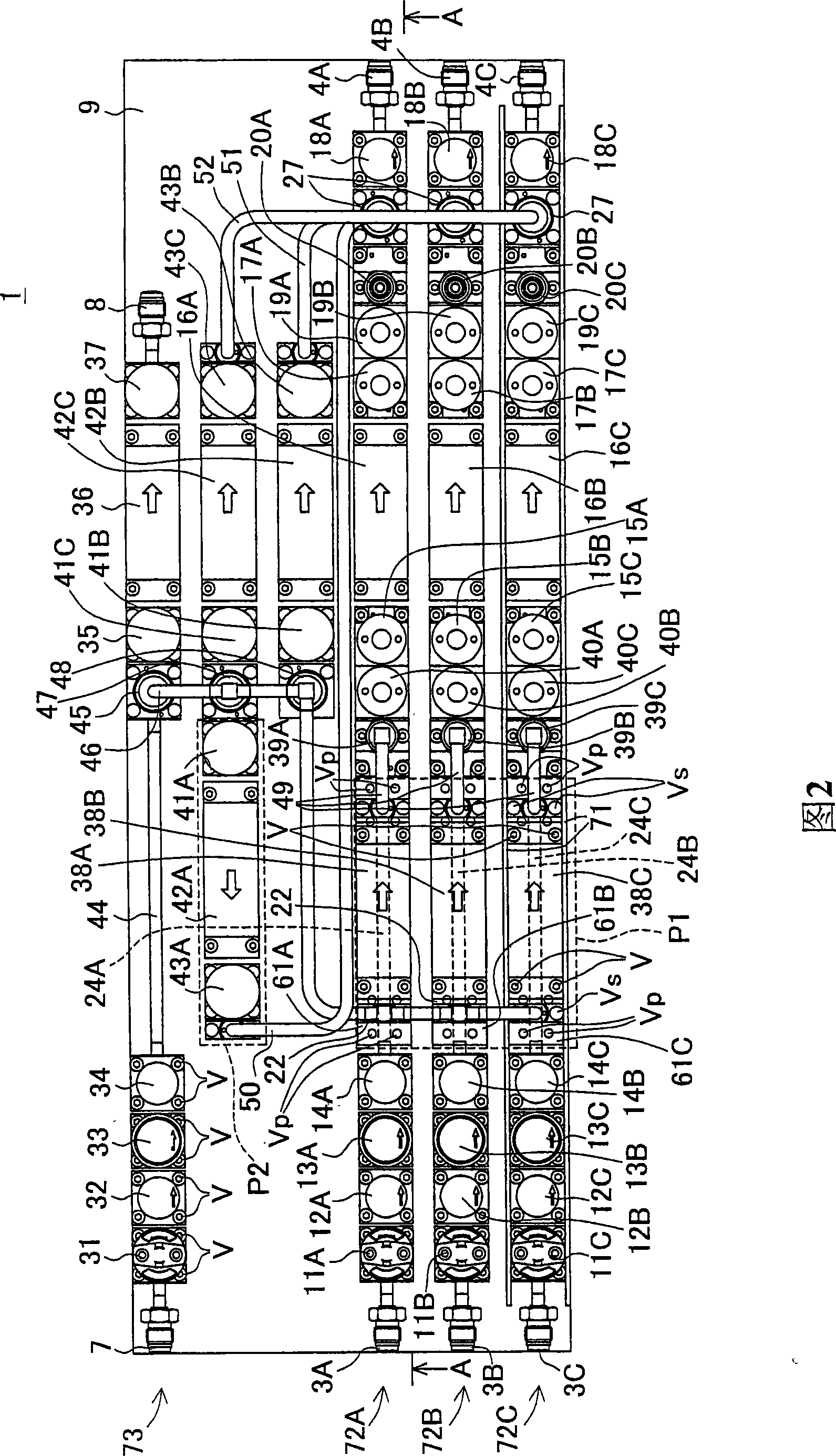
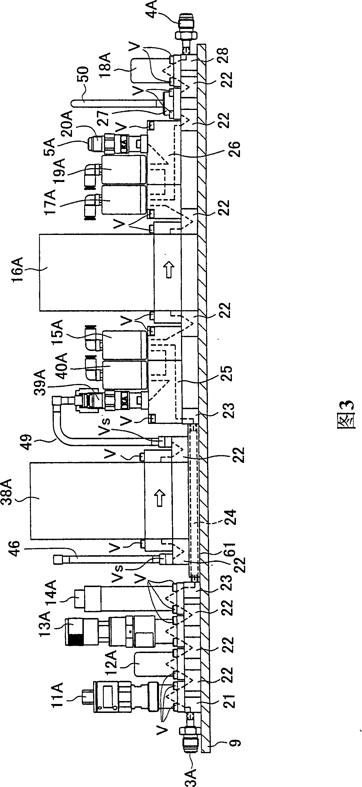
[0024] Next, one embodiment of the gas integration unit of the present invention will be described with reference to the drawings.

[0025] (circuit description)

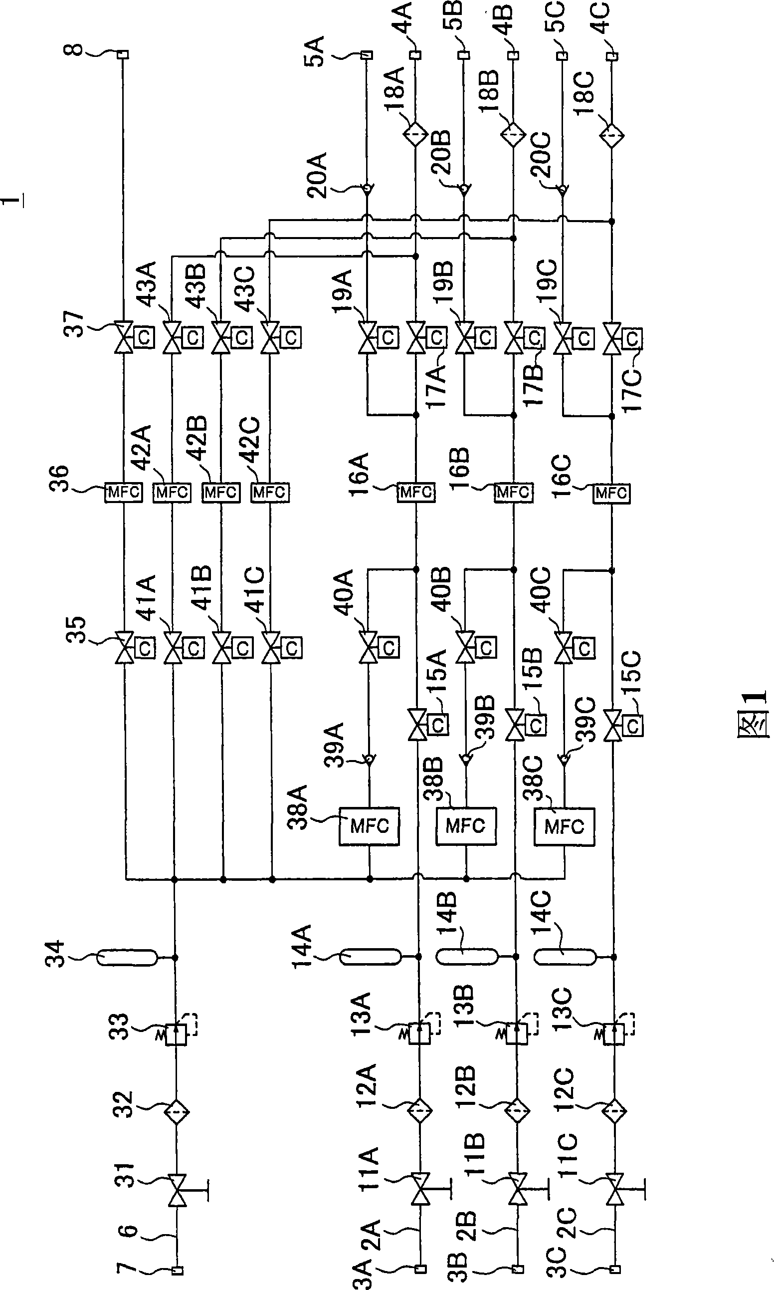
[0026] figure 1 is a circuit diagram of the gas integration unit 1.

[0027] The gas integration unit 1 is arranged between an unillustrated gas tank and an unillustrated processing chamber. In order to supply a certain amount of working gas from the unillustrated gas tank to the unillustrated processing chamber each time, a second One to the third process gas pipelines 2A, 2B, 2C. Furthermore, the gas integration unit 1 is provided with a purge gas line 6 for cleaning the first to third process gas lines 2A, 2B, and 2C.

[0028] A plurality of fluid control means are provided in the first to third process gas lines 2A, 2B, and 2C. The manual valves 11A, 11B, and 11C are connected to unillustrated gas tanks through operating gas inlets 3A, 3B, and 3C. Manual valves 11A, 11B, 11C are connected to first process s...


PUM


Abstract

The present invention provides a gas integration unit capable of reducing base space. In the gas integration unit, setting first gas units (72A, 72B, 72C), for controlling the supply of a first gas; a second gas unit (73), connecting with the first gas units (72A, 72B, 72C) and controlling cleaning gas converging to the first gas units (72A, 72B, 72C) by means of a plurality of fluid control components (31 to 34, 38A to 43a, 38B to 43B, 38C to 43C); and stackup blocks (61A, 61B, 61C), stacking on the first gas units (72A, 72B, 72C) and stacking parts (38A 38B, 38C) of the fluid control components on the stackup blocks (61A, 61B, 61C).

Description

technical field [0001] The invention relates to a gas integration unit with a gas unit and a purge gas unit. Background technique [0002] Conventionally, in a semiconductor manufacturing apparatus, a constant amount of working gas is supplied to a wafer in a processing chamber at a time to form a film on the wafer. Wafers are supplied with various working gases and laminated to form a film. Since the flow rate of the working gas affects the film formation quality, the semiconductor manufacturing apparatus arranges a gas integration unit equipped with a plurality of process gas units for controlling the supply of the working gas on the upstream side of the processing chamber. [0003] In order to improve the quality of film formation, it is necessary to strictly control the components of the working gas supplied to the wafer. Therefore, in the gas integration unit, the purge gas unit is connected to each process gas unit to combine the purge gas and remove the working gas ...

Claims


Application Information

Patent Timeline
Patent Type & Authority Patents(China)
IPC IPC(8): C23C16/44H01L21/00H01L21/205H01L21/285
CPCH01L21/67017C23C16/45561
Inventor 荻原立典井上贵史稻垣竹矢
Owner CKD
Learn More