Self-locking type flow control valve

A flow control valve, self-locking technology, applied in the direction of lift valve, safety valve, balance valve, etc., can solve the problems of environmental pollution, waste of pipe network resources, high cost, etc., to reduce environmental pollution, reduce labor intensity, and easy to manufacture Effect

Active Publication Date: 2018-02-02
CHINA MCC17 GRP
View PDF6 Cites 0 Cited by
  • Summary
  • Abstract
  • Description
  • Claims
  • Application Information

AI Technical Summary

Problems solved by technology

[0002] Current engineering buildings and civil facilities often involve pipeline connection parts. The previous manual flow control valves and self-operated flow control valves are extremely inconvenient to use and have many shortcomings: 1. Failure to cut off the flow in time when there is a sudden burst in the pipe network The phenomenon not only causes waste of resources but also causes environmental pollution; 2. Once the pipe network installed in the pipe gallery catches fire, especially in places with power supply, it is not easy to use water to extinguish the fire, which poses a great safety hazard; 3. The manufacture is cumbersome, large in size and high in cost. ; 4. Poor versatility; 5. The installation process is time-consuming and labor-intensive; 6. The control valve for hydraulic power is particularly polluting to the environment, and the control valve for gas will aggravate the flame; 7. It is inconvenient to install and troubleshoot; 8. Especially Once the electric flow control valve is powered off, the flow cannot be cut off in time

Method used


Image

  • Self-locking type flow control valve
  • Self-locking type flow control valve

Examples


Embodiment 1

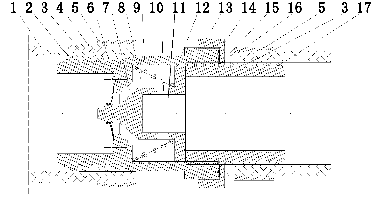
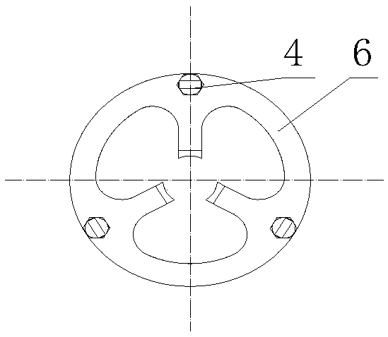
[0025] like Figure 1-2 As shown, a self-locking flow control valve in this embodiment includes a main body, the main body is a cylindrical structure, a branch pipe 1 is connected to the left side of the main body, and a main pipe 16 is connected to the right side of the main body; the above-mentioned main body It is composed of pipe head piece 2, valve core 12, curved shrapnel 6 and stack spring 9; pipe head piece 2 is a structure with a trumpet-shaped closing opening in the inner hole, and pipe head piece 2 is inserted at the port of branch pipe 1, and the main pipe In the end hole of 16, be connected with main pipe head piece 17, and main pipe head piece 17 is the construction of a left-hand outer diameter band tapered mouth. The above-mentioned pipe head piece 2 and the main pipe head piece 17 are screwed through the nut 13; the middle part of the pipe head piece 2 is provided with an inward boss, and the left end surface of the inner boss is provided with evenly distribut...


PUM


Abstract

The invention discloses a self-locking type flow control valve and belongs to the technical field of building pipe network safety devices. The self-locking type flow control valve comprises a main body; the left side of the main body is connected with a branch pipe, and the right side of the main body is connected with a main pipe; the main body is composed of a pipe head piece, a valve element, acurve elastic piece and a heap-shaped spring; the main pipe head piece is connected in a hole in the end of the main pipe; the curve elastic piece is fixedly connected to a boss of a left side innerhole of the pipe head piece; a toothed groove is formed in the outer diameter of the left side of the pipe head piece and sleeved with a flexible lining; the branch pipe and the flexible lining are fixed through a pipe hoop; the right side of the pipe head piece is connected with an outer screw thread for screwed connection, and an inner screw thread for adjustment is machined at the inner diameter of the right side of the pipe head piece; a heap-shaped spring cavity is formed in a right side hole of the pipe head piece; a throttling opening is formed at one corner of the heap-shaped spring cavity; and the heap-shaped spring is placed in the heap-shaped spring cavity. The self-locking type flow control valve is convenient and humanized in structural design and has the advantages of being convenient to mount, easy to manufacture, high in universality, safe, reliable, long in life and the like.

Description

technical field [0001] The invention relates to the technical field of building pipe network safety devices, and more specifically relates to a self-locking flow control valve. Background technique [0002] Current engineering buildings and civil facilities often involve pipeline connection parts. The previous manual flow control valves and self-operated flow control valves are extremely inconvenient to use and have many shortcomings: 1. Failure to cut off the flow in time when there is a sudden burst in the pipe network The phenomenon not only causes resource waste but also causes environmental pollution; 2. Once the pipe network installed in the pipe gallery catches fire, especially in places with power supply, it is not easy to use water to extinguish the fire, which poses a great safety hazard; 3. The manufacturing is cumbersome, large in size and high in cost. ; 4. Poor versatility; 5. The installation process is time-consuming and labor-intensive; 6. The control valve ...

Claims


Application Information

Patent Timeline
Patent Type & Authority Applications(China)
IPC IPC(8): F16K17/30F16K17/36F16K1/38
CPCF16K1/385F16K17/30F16K17/36
Inventor 战洪波时华钢谈文李新
Owner CHINA MCC17 GRP
Why Eureka
Try Eureka