
A conventional pull-in sensor protective cover device

A technology of protective cover and sensor, applied in the direction of measuring device, machine/structural component test, vibration test, etc., to achieve the effect of convenient assembly and disassembly, heat insulation and electromagnetic radiation avoidance

Active Publication Date: 2019-07-05
UNIV OF SCI & TECH BEIJING
View PDF7 Cites 0 Cited by
  • Summary
  • Abstract
  • Description
  • Claims
  • Application Information

AI Technical Summary

Problems solved by technology

[0006] The technical problem to be solved by the present invention is to solve the problem that the harsh working environment factors affect the measurement accuracy of the sensor in the current vibration test. In order to overcome the above defects, the present invention provides a new type of conventional suction-type sensor protective cover, which is installed outside the sensor. It is used to protect the sensor. Through reasonable design of its structure, it can prevent dirt and liquid from entering the protective cover to damage the sensor, and at the same time prevent the sensor from being affected by the external temperature field, electromagnetic field, etc., prolong the service life of the sensor, and ensure the accuracy and accuracy of the measurement. suitable for promotion

Method used


Image

  • A conventional pull-in sensor protective cover device
  • A conventional pull-in sensor protective cover device
  • A conventional pull-in sensor protective cover device

Examples


Embodiment Construction

[0047] In order to make the technical problems, technical solutions and advantages to be solved by the present invention clearer, the following will describe in detail with reference to the drawings and specific embodiments.

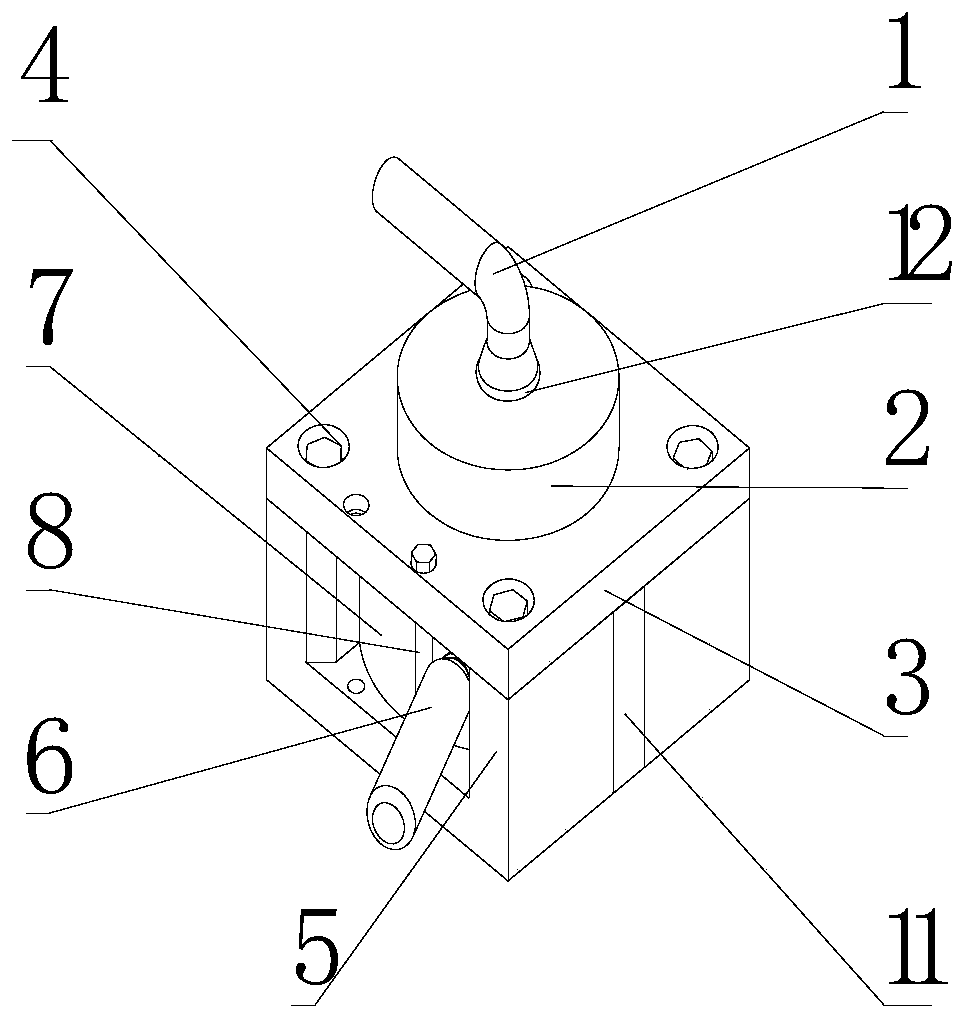
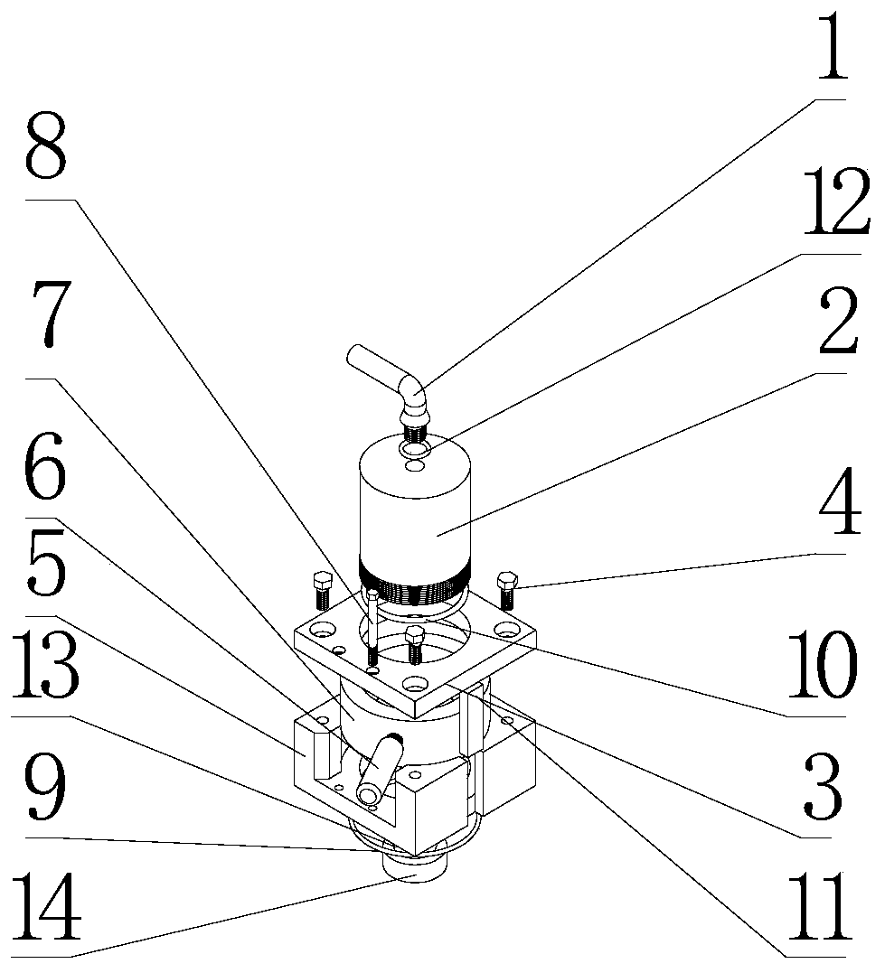
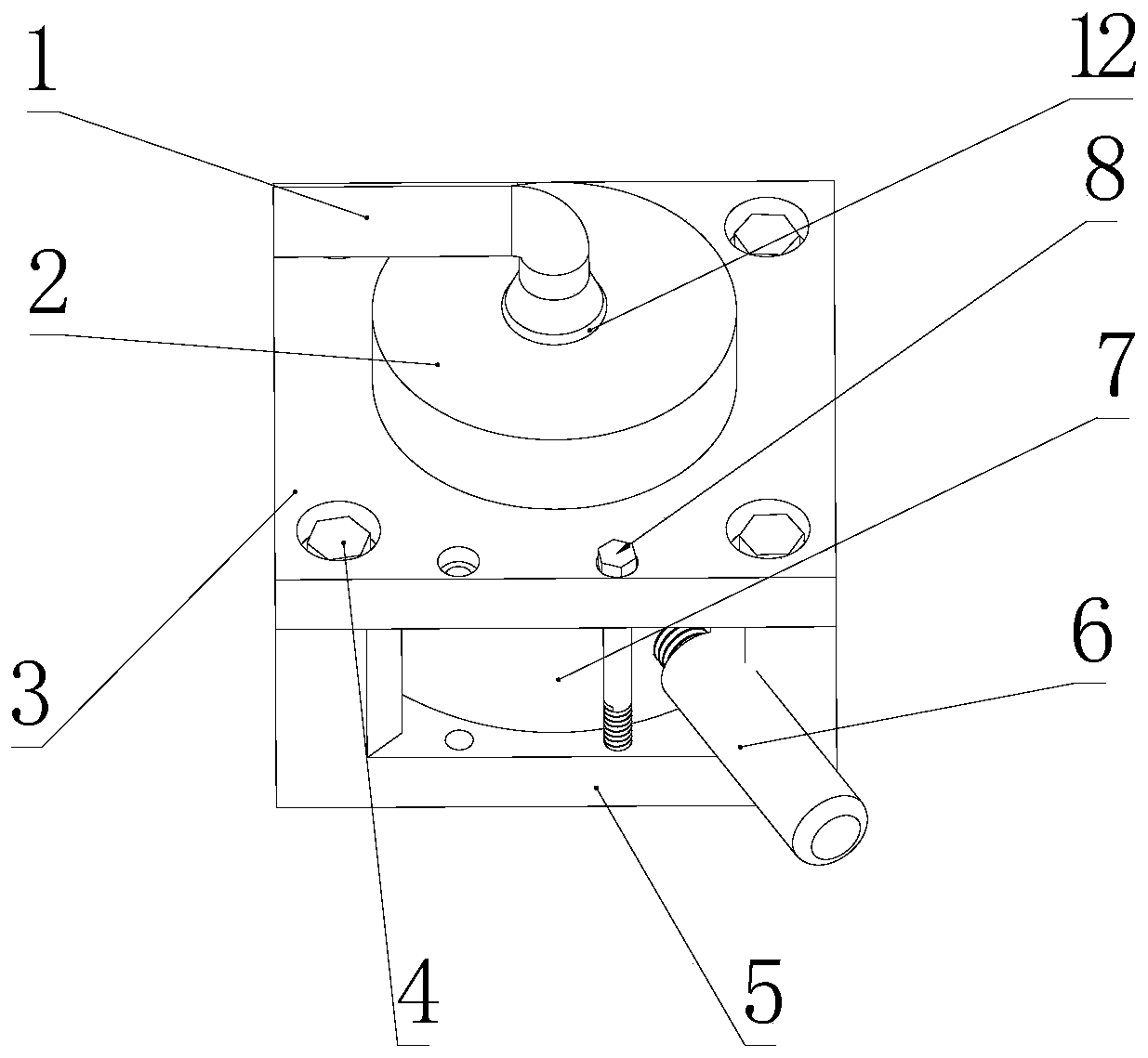
[0048] Such as Figure 1 to Figure 7 As shown, in this embodiment, the magnetic base 5 is mainly made of ferromagnetic material, and a non-magnetic material is clamped in the middle of the vertical direction with the magnetic base 5, that is, the spacer magnet 11, and a center is provided in the vertical direction of the center of the magnetic base 5 end face. Hole, the center hole penetrates the upper end cover 3 of the magnetic base, a rotatable ring magnet 7 is installed in the center hole, and a handle 6 is connected to the ring magnet 7, the magnetic field of the ring magnet 7 can be adjusted in the horizontal direction by rotating the handle 6, and the ring The center of the magnet 7 is equipped with a circular protective cover body 2, and the sens...


PUM


Abstract

The invention provides a conventional attracted type sensor protective cover device, which aims to perform liquid and high temperature insulation protection on a conventional non-waterproof sensor inthe vibration monitoring / detecting process under severe conditions such as water mist, oil liquid and high-temperature radiation and reduce strict requirements of a testing environment for the equipment. The conventional attracted type sensor protective cover device provided by the invention comprises a circular protective cover body, an upper end cover, an annular magnet, a magnetic isolating body, a handle, a magnet base, O-shaped sealing rings, a waterproof guide pipe, connecting bolts, a limit bolt and a coating material, and is characterized in that the magnet base is made of a ferromagnetic material, and a non-magnetic material is clamped at the middle part in the direction perpendicular to the magnet base; the center of the magnet base is provided with a cylindrical hole groove in the vertical direction, the central hole is internally provided with the rotatable annular magnet, the annular magnet is connected to the handle, the center of the annular magnet is provided with the circular protective cover body, the lower end of the cover body is provided with a screw thread and is connected to the bottom end of the magnet base, the upper end of the cover body is connected withthe waterproof guide pipe, and the lower end of the magnet base is embedded with the O-shaped sealing ring. The conventional attracted type sensor protective cover device is convenient to assemble anddisassemble and suitable for popularization.

Description

technical field [0001] The invention relates to a conventional pull-in type sensor protective cover device, in particular to a protective cover for a vibration test sensor. Background technique [0002] A sensor is a detection device that can sense the measured information, and can change the sensed information into electrical signals or other required forms of information output according to certain rules, so as to meet the requirements of information transmission, processing, storage, display, recording and control requirements. [0003] At present, the vibration test system has been widely used in the monitoring and maintenance process of the vibration state of important instruments and equipment, and the key component for collecting vibration signals is the sensor. The sensor is a high-precision measuring device, and its measurement accuracy directly affects the accuracy of its data collection. This result deviation will have a greater impact on subsequent research and ...

Claims


Application Information

Patent Timeline
Patent Type & Authority Patents(China)
IPC IPC(8): G01M7/02
CPCG01M7/025
Inventor 陈兵刘昌张利杰莫威
Owner UNIV OF SCI & TECH BEIJING
Learn More