Illumination assembly and ultraviolet light liquid crystal illuminating machine

A technology of lighting components and ultraviolet rays, applied in optics, nonlinear optics, instruments, etc., can solve problems such as affecting the optical performance of liquid crystal displays, low yield, and reducing product yield.

Active Publication Date: 2018-02-02
SHENZHEN CHINA STAR OPTOELECTRONICS SEMICON DISPLAY TECH CO LTD
View PDF5 Cites 5 Cited by
  • Summary
  • Abstract
  • Description
  • Claims
  • Application Information

AI Technical Summary

Problems solved by technology

The moving time of the shading plate of the existing G8.5 generation production line is about 5s. Combining the two actions of opening and closing, the central point takes about 10s more irradiation time than the two side edges, which leads to the existence of pre-tilt angles between the two side edges and the center point. Inconsistencies, which affect the optical performance o

Method used


Image

  • Illumination assembly and ultraviolet light liquid crystal illuminating machine
  • Illumination assembly and ultraviolet light liquid crystal illuminating machine
  • Illumination assembly and ultraviolet light liquid crystal illuminating machine

Examples


Embodiment Construction

[0026] The following will clearly and completely describe the technical solutions in the embodiments of the present invention with reference to the accompanying drawings in the embodiments of the present invention. Obviously, the described embodiments are only part of the embodiments of the present invention, not all of them. Based on the embodiments of the present invention, all other embodiments obtained by persons of ordinary skill in the art without making creative efforts belong to the protection scope of the present invention.

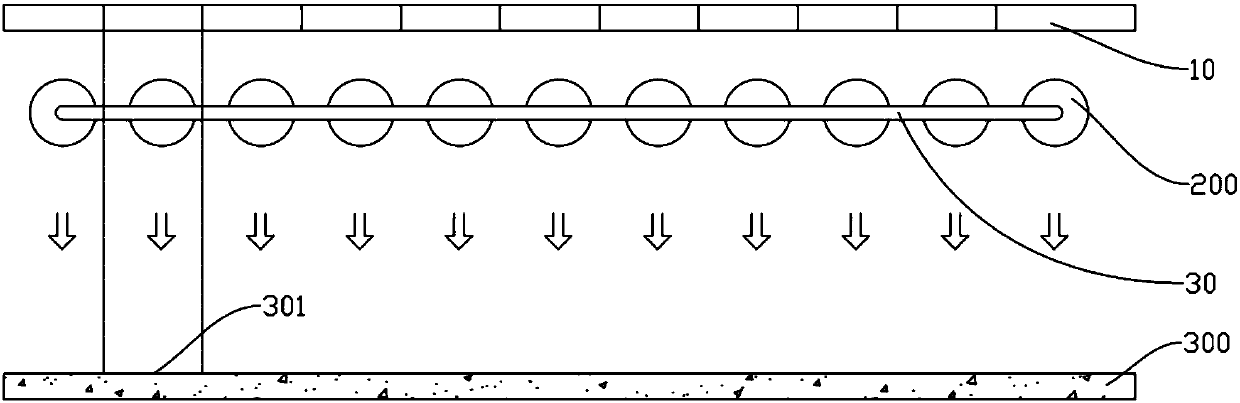
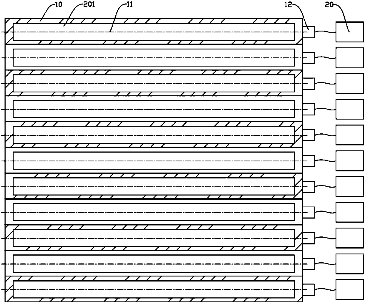
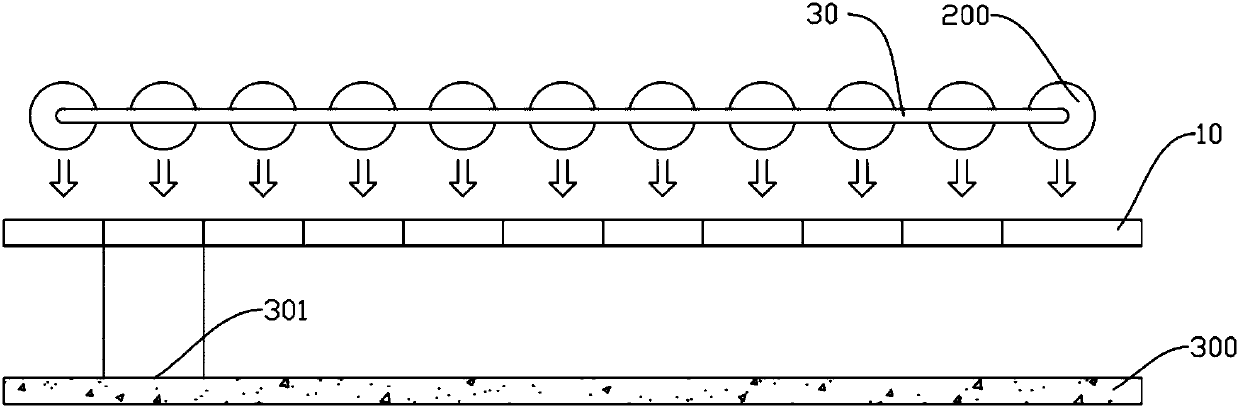
[0027] see figure 1 , figure 2 with image 3 The lighting assembly 100 is used to control the irradiation time to the substrate 300 in the ultraviolet irradiation machine, including a lamp tube 200, a shading plate 10 and a driving device 20, the lamp tube 200 is used to irradiate the substrate 300, and the shading plate 10 is connected to the driving device 20, so that the driving device 20 drives the shading plate 10 to turn over between the...


PUM


Abstract

The invention relates to the field of LCD displayer manufacturing, and discloses an illumination assembly used for controlling the illumination time of lamp tubes on a substrate in an ultraviolet light illuminating machine in the ultraviolet light aligning working process. The illumination assembly includes multiple shading plates, and at least one end of each shading plate is connected with a driving device for controlling; when the shading plates are arranged, each shading plate has an independent axis, and by overturning the shading plates around the corresponding lamp tubes, the switch-onand switch-off states of each lamp tube can be achieved. Each shading plate can be overturned to a first position and a second position, and therefore it is ensured that the ultraviolet illumination time of each area of the substrate is equal, the illumination uniformity is controlled, and uniform pretilt angles can be maintained on liquid crystals.

Description

technical field [0001] The invention relates to the field of liquid crystal display manufacture, in particular to an ultraviolet light alignment process. Background technique [0002] The ultraviolet light alignment process is a technology in the cell-to-cell manufacturing process of LCD displays. By irradiating ultraviolet light to the substrate, the reactive monomers in the liquid crystal react, so that the liquid crystal forms a pre-tilt angle. The size of the pretilt angle and the exposure time are in direct proportion. The longer the time, the larger the pretilt angle. Lighting time needs to be strictly controlled. [0003] The UV alignment process needs to use a UV liquid crystal irradiation machine to emit ultraviolet light. At present, metal halide lamps, mercury lamps and fluorescent lamps are commonly used. In actual production, these lamps use the shape of lamp tubes arranged side by side to irradiate the substrate, and the time for each substrate to be irradiat...

Claims


Application Information

Patent Timeline
IPC IPC(8): G02F1/1337
CPCG02F1/133788
Inventor 赵仁堂
Owner SHENZHEN CHINA STAR OPTOELECTRONICS SEMICON DISPLAY TECH CO LTD
Why Eureka
Try Eureka