
Novel control cabinet connection device

A connection device and control cabinet technology, which is applied in the field of control cabinets, can solve the problems of inconvenient access and space occupation, and achieve the effects of convenient access, uniform rotation load, and uniform load bearing

Pending Publication Date: 2018-02-02
TIANJIN HRCT TECH CO LTD
View PDF0 Cites 0 Cited by
  • Summary
  • Abstract
  • Description
  • Claims
  • Application Information

AI Technical Summary

Problems solved by technology

[0002] In the process of using the control cabinet, tools such as wrenches, screwdrivers, etc. are often required for maintenance and repair, and these tools need to be carried by maintenance personnel or stored in other places, occupying space and inconvenient to access

Method used


Image

  • Novel control cabinet connection device
  • Novel control cabinet connection device
  • Novel control cabinet connection device

Examples


Embodiment Construction

[0016] Below according to accompanying drawing and embodiment the present invention will be described in further detail:

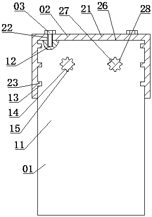
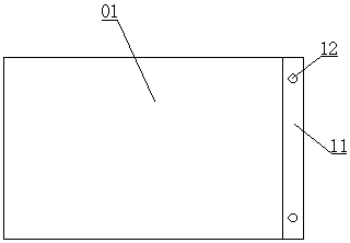
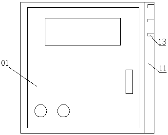
[0017] A new type of control cabinet connection device, including a control cabinet 01, a storage box 02, and a fixing bolt 03. The right part of the control cabinet 01 has a connection frame 11, and internal thread grooves 12 are symmetrically distributed on the top of the connection frame 11. The left side of the storage box 02 There is a fixed frame 21 inside the fixed frame 21, which has an assembly groove 26 inside, and threaded through holes 22 are symmetrically distributed inside the assembly groove 26. The fixing bolt 03 is inserted into the internal thread groove 12 and the threaded through hole 22, and the control cabinet 01 is connected with the storage box 02. Slider grooves 13 are evenly distributed outside the connecting frame 11, and sliders 23 are evenly distributed inside the assembly groove 26. The sliders 23 are inserted into the slider g...


PUM


Abstract

The invention provides a novel control cabinet connection device which comprises a control cabinet, a storage box and a fixed bolt. A right part of the control cabinet has a connection box, and an internal thread groove is symmetrically distributed at the top of the connection box. A left part of the storage box has a fixed frame which has an assembly groove inside. A thread through hole is symmetrically distributed in the assembly groove. The fixed bolt is inserted into the internal thread groove and the thread through hole. The control cabinet is connected to the storage box. Slider groovesare uniformly distributed at the outer part of the connection box. Sliders are uniformly distributed in the assembly groove. The sliders are inserted into the slider grooves and slide with the slidergrooves. Positioning tooth column grooves are uniformly distributed outside the connection box. Tooth grooves are uniformly distributed in the positioning tooth column grooves. Positioning tooth columns are uniformly distributed in the assembly groove. External teeth are uniformly distributed at the outer parts of the positioning tooth columns. The positioning tooth columns are inserted into the positioning tooth column grooves, and the external teeth are matched with the tooth grooves.

Description

technical field [0001] The invention relates to the field of control cabinets, in particular to a novel control cabinet connection device. Background technique [0002] During the use of the control cabinet, tools such as wrenches and screwdrivers are often required for maintenance and repair, and these tools need to be carried by maintenance personnel or stored in other places, occupying space and inconvenient to access. Contents of the invention [0003] The present invention aims at the above-mentioned deficiencies existing in the prior art, and provides a novel control cabinet connection device which is convenient to use and stable in connection. [0004] The purpose of the present invention is to realize through the following technical solutions: [0005] A new type of control cabinet connection device, including a control cabinet, a storage box, and fixing bolts. The right part of the control cabinet has a connection frame, and internal thread grooves are symmetri...

Claims


Application Information

Patent Timeline
IPC IPC(8): H05K5/02
CPCH05K5/0217
Inventor 李家升
Owner TIANJIN HRCT TECH CO LTD
Learn More