Mechanical arm and laser processing equipment

A technology of manipulators and manipulators, applied in laser welding equipment, metal processing equipment, manipulators, etc., can solve the problems of inconsistency in the direction of silicon wafer transmission, rising, and difficulties in the screen printing process, so as to facilitate transmission and processing and ensure transmission The effect of simple direction and structure

Active Publication Date: 2018-02-06
WUHAN DR LASER TECH CORP LTD
View PDF7 Cites 6 Cited by
  • Summary
  • Abstract
  • Description
  • Claims
  • Application Information

AI Technical Summary

Problems solved by technology

However, there are still some technical problems with these devices. First, although the production capacity has been greatly improved, there is still a lot of room for improvement.
Second, during the

Method used


Image

  • Mechanical arm and laser processing equipment
  • Mechanical arm and laser processing equipment
  • Mechanical arm and laser processing equipment

Examples


Embodiment 1

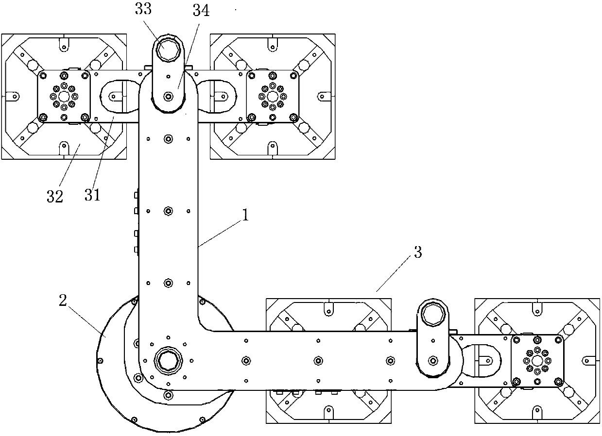
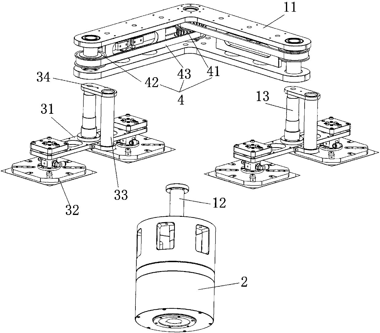
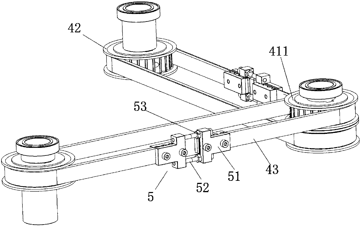
[0035] Embodiment one: if Figures 1 to 3 As shown, the manipulator of this embodiment includes a rotating arm 1, a driving device 2 and a suction cup assembly 3, the driving end of the above-mentioned driving device 2 is arranged vertically upward, the above-mentioned rotating arm 1 is horizontally installed on the driving end of the above-mentioned driving device 2, and the above-mentioned suction cup The assembly 3 is horizontally and rotatably arranged on the free end of the above-mentioned rotating arm 1, and is connected with the driving end of the above-mentioned driving device 2 through the transmission mechanism 4, and the above-mentioned driving device 2 can respectively drive the above-mentioned rotating arm 1 and the suction cup assembly 3 through the above-mentioned transmission mechanism 4 Synchronous reverse rotation.

[0036] Driven by the driving device 2, the synchronous reverse rotation of the rotating arm 1 and the suction cup assembly 3 is realized, ensuri...

Embodiment 2

[0047] Embodiment two: if Figure 4 and 5 As shown, the laser processing equipment of this embodiment includes a feeding and conveying assembly 18, an unloading and conveying assembly 19, a laser processing host 21, a cell processing table 20 and a workbench 22, the above-mentioned feeding and conveying assembly 18, the unloading and conveying assembly 19 1. The laser processing host 21 and the cell processing table 20 are respectively installed on the above-mentioned workbench 22. The above-mentioned laser processing host 21 is located above the above-mentioned cell processing table 20, and also includes the above-mentioned manipulator in Embodiment 1. The above-mentioned manipulator is installed on the above-mentioned workbench. On the platform 22, and located on one side of the above-mentioned cell sheet processing platform 20, the above-mentioned feeding and conveying assembly 18 and the above-mentioned unloading and conveying assembly 19 are respectively installed on the ...


PUM


Abstract

The invention relates to a mechanical arm and laser processing equipment. The mechanical arm comprises a rotating arm, a driving device and a suction cup assembly, the driving end of the driving device is vertically arranged, and the rotating arm is horizontally installed at the driving end of the driving device; the suction cup assembly is horizontally and rotationally arranged at the free end ofthe rotating arm, and is connected with the driving end of the driving device through a transmission mechanism; the driving device can drive the rotating arm and the suction cup assembly to synchronously rotate reversely through transmission mechanisms respectively. The mechanical arm has the advantages that the structure is simple, the design is reasonable, it can be ensured that the angle of the suction cup assembly cannot be changed in the working process of the mechanical arm, and therefore it is guaranteed that the angle of a to-be-machined workpiece sucked by the suction cup assembly does not change; it is ensured that the conveying directions of feeding and discharging of the workpiece is consistent, subsequent workpiece conveying and machining are facilitated, and the productivityis improved.

Description

technical field [0001] The invention relates to the technical field of laser processing, in particular to a manipulator and laser processing equipment. Background technique [0002] As photovoltaic solar cells are paid more and more attention and attention by governments and people of more and more countries, solar cells are more and more used in human life. Higher requirements are put forward for solar cell production equipment, and laser processing equipment with high efficiency and large capacity needs to be developed urgently. [0003] In order to improve production capacity, laser processing equipment companies have also invested a lot of energy in technological innovation. In the existing technology, laser processing equipment has also developed from single-line equipment to dual-line laser processing equipment, which greatly improves the processing capacity of high-precision laser equipment. However, there are still some technical problems with these devices. First, ...

Claims


Application Information

Patent Timeline
IPC IPC(8): B23K26/70B25J15/06B65G47/91
CPCB23K26/702B25J15/0616B65G47/91
Inventor 李志刚卫哲李远鹏
Owner WUHAN DR LASER TECH CORP LTD
Why Eureka
Try Eureka