Lens driving device

A lens driving device and lens technology, applied in projection devices, printing devices, focusing devices, etc., can solve the problems of local intensity weakening, unfavorable miniaturization of lens driving devices, short circuit or jamming, etc.

Active Publication Date: 2018-02-06
TDK TAIWAN
View PDF5 Cites 18 Cited by
  • Summary
  • Abstract
  • Description
  • Claims
  • Application Information

AI Technical Summary

Problems solved by technology

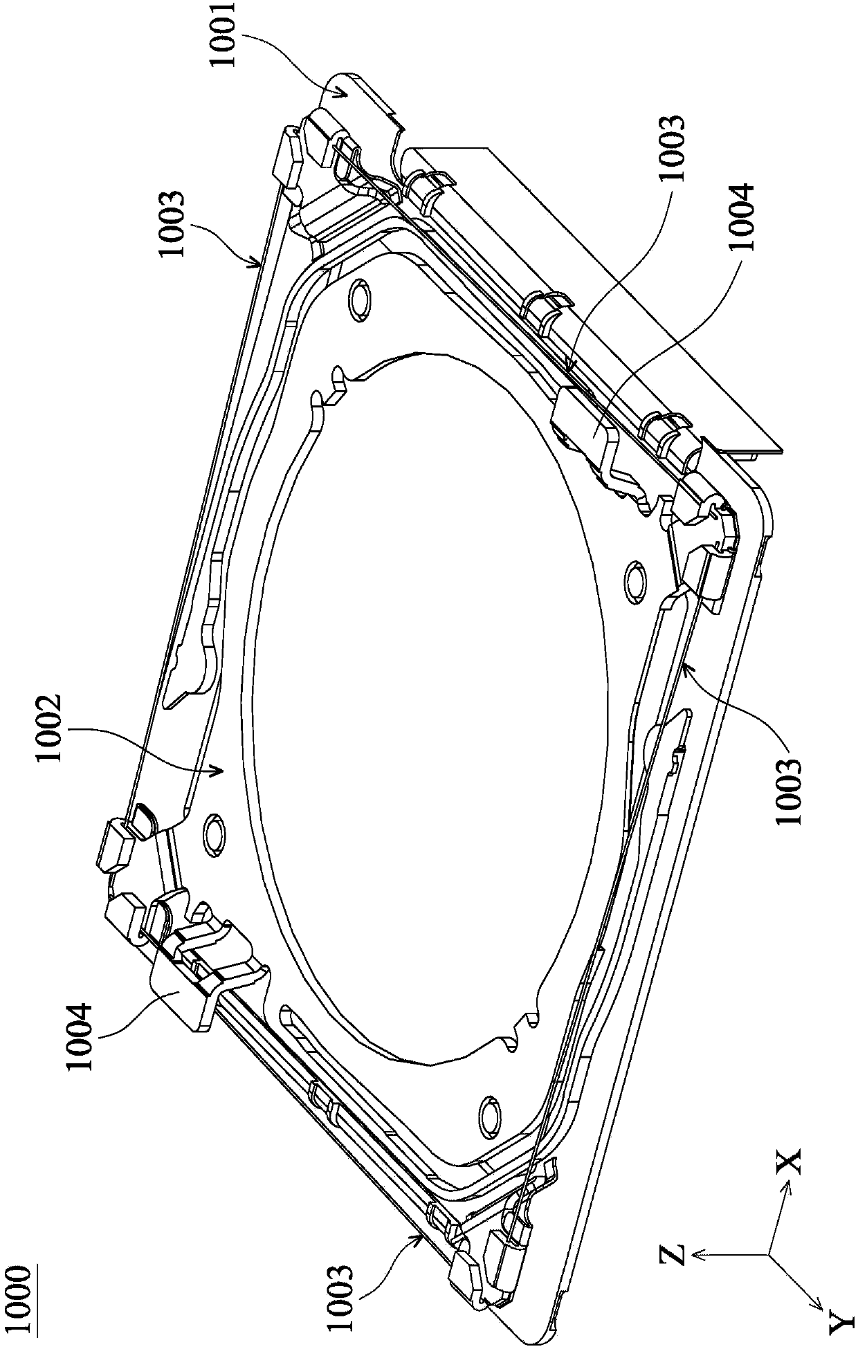
[0004] However, in order to achieve the electrical connection between the aforementioned optical anti-shake mechanism 1000 and the lens module, it is necessary to form a plurality of gooseneck members 1004 extending toward the direction of the lens module above the movable member 1002 (with lines formed thereon), and The base of the lens module needs to reserve a space (groove) for accommodating the gooseneck member 1004, so that the size of the lens module will increase and the local strength of the base will be weakened (because the thickness near the groove is reduced)
In addition, in order to avoid possible short circuit or jamming of the memory alloy wire 1003 in contact with the gooseneck member 1004 during the operation of the mechanism, the gooseneck member 1004 also needs to be configured at a certain distance from the memory alloy wire 1003, so that the optical hand-proof The size of the shock mechanism 1000 will increase, which is not conducive to the miniaturization of the lens driving device

Method used


Image

  • Lens driving device
  • Lens driving device
  • Lens driving device

Examples


Embodiment Construction

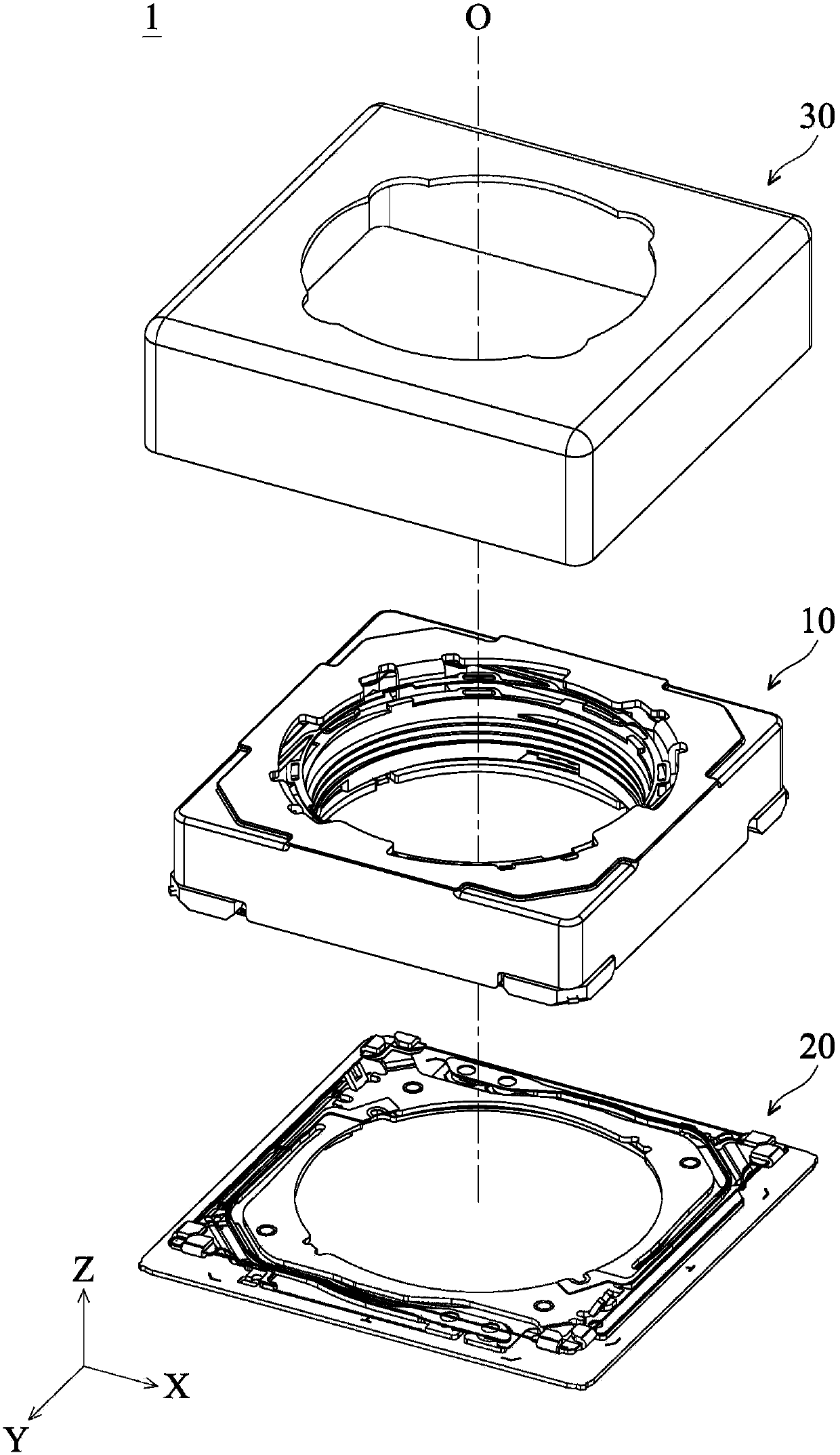
[0089] A lens driving device according to an embodiment of the present invention will be described below. It should be readily appreciated, however, that the embodiments of the invention provide many suitable inventive concepts that can be implemented in a wide variety of specific contexts. The specific embodiments disclosed are merely illustrative of specific ways to use the invention and do not limit the scope of the invention. The scope of protection of the present invention should be determined by the scope defined by the appended claims.

[0090] Unless otherwise defined, all terms (including technical and scientific terms) used hereinafter have the same meaning as commonly understood by those skilled in the art. It is understood that these terms, such as those defined in commonly used dictionaries, should be interpreted as having a meaning consistent with the background or context of the related art and the present disclosure, rather than in an idealized or overly forma...


PUM


Abstract

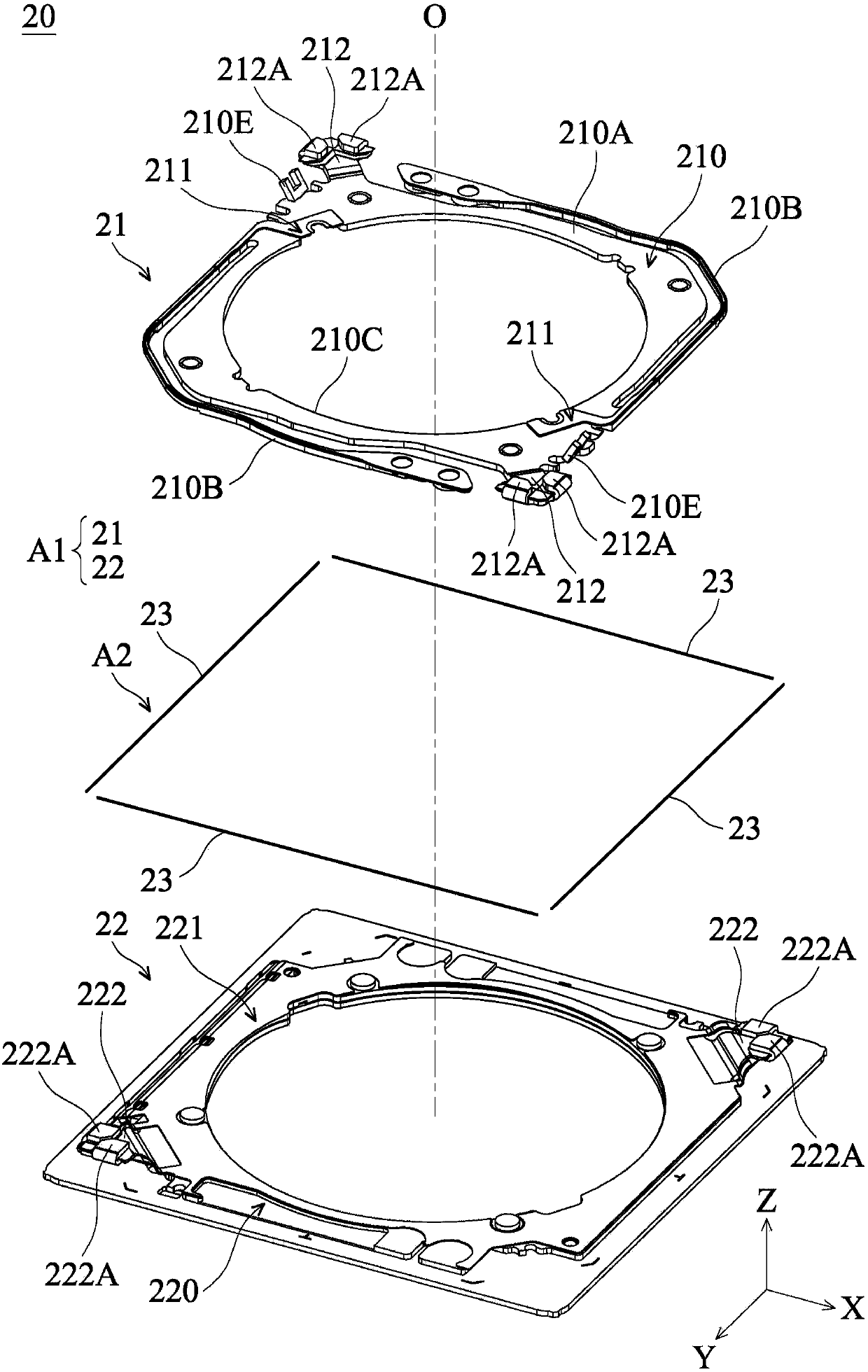
A lens driving device is provided, including a base, a holder, a first driving mechanism disposed on the first side of the base, a second driving mechanism disposed on the second side of the base opposite the first side, and a conductive member disposed on the base. The holder is configured to sustain a lens. The first driving mechanism is configured to force the holder to move along the optical axis of the lens. The second driving mechanism includes a circuit board assembly and a shape memory alloy (SMA) wire assembly configured to force the base to move in the plane perpendicular to the optical axis. The conductive member and the circuit board assembly are connected at an electrical connection point, and the SMA wire assembly is closer to the light-incident end of the lens with respect to the electrical connection point.

Description

technical field [0001] The present invention relates to a lens driving device; in particular, to a lens driving device using shape memory alloy (Shape Memory Alloy, SMA) wires to move the lens. Background technique [0002] Under the trend of miniaturization of lens driving devices, many handheld digital products (handheld devices) such as mobile phones or tablet computers have built-in camera or video recording functions. Based on users' increasing demands on image quality, lens driving devices with Optical Image Stabilization (OIS) functions have become mainstream. [0003] figure 1 A schematic diagram of an optical image stabilization (OIS) mechanism 1000 of a conventional lens driving device is shown. As shown in the figure, the optical anti-shake mechanism 1000 mainly includes a support member 1001, a movable member 1002 and a plurality of memory alloy (SMA) wires 1003, wherein the memory alloy wire 1003 is arranged between the support member 1001 and the movable memb...

Claims


Application Information

Patent Timeline
Patent Type & Authority Applications(China)
IPC IPC(8): G03B5/00G03B13/34
CPCG03B5/00G02B7/09G03B13/36H04N23/687G02B7/08G02B27/646G03B3/10G03B5/02G03B2205/0015G03B2205/0076G02B13/001G03B5/04G03B29/00G03B2205/0007H05K1/144H05K1/181H05K2201/10121H05K2201/10227
Inventor 胡朝彰郭侲圻
Owner TDK TAIWAN
Why Eureka
Try Eureka