Broadband miniaturized patch antenna

A patch antenna and broadband technology, applied in the field of wireless communication, can solve problems such as poor consistency, and achieve the effect of compact structure and good consistency

Inactive Publication Date: 2018-02-23
UNIV OF ELECTRONICS SCI & TECH OF CHINA
View PDF5 Cites 4 Cited by
  • Summary
  • Abstract
  • Description
  • Claims
  • Application Information

AI Technical Summary

Problems solved by technology

Typical examples include E-type patch antennas, U-slot patch antennas, V-slot patch antennas, and ψ-type patch antennas, etc. However, the biggest disadvantage of these antennas is that the directional consistency is not very good in the entire operating bandwidth

Method used


Image

  • Broadband miniaturized patch antenna
  • Broadband miniaturized patch antenna
  • Broadband miniaturized patch antenna

Examples


Embodiment Construction

[0016] The bandwidth and gain of traditional patch antennas can be improved by using parasitic patches, and the miniaturization of antennas can be achieved by using RIS surfaces.

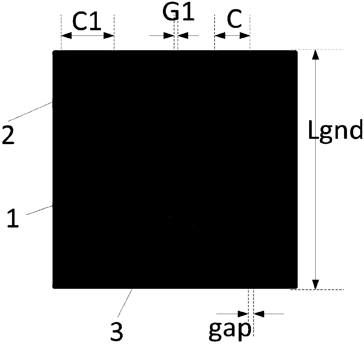
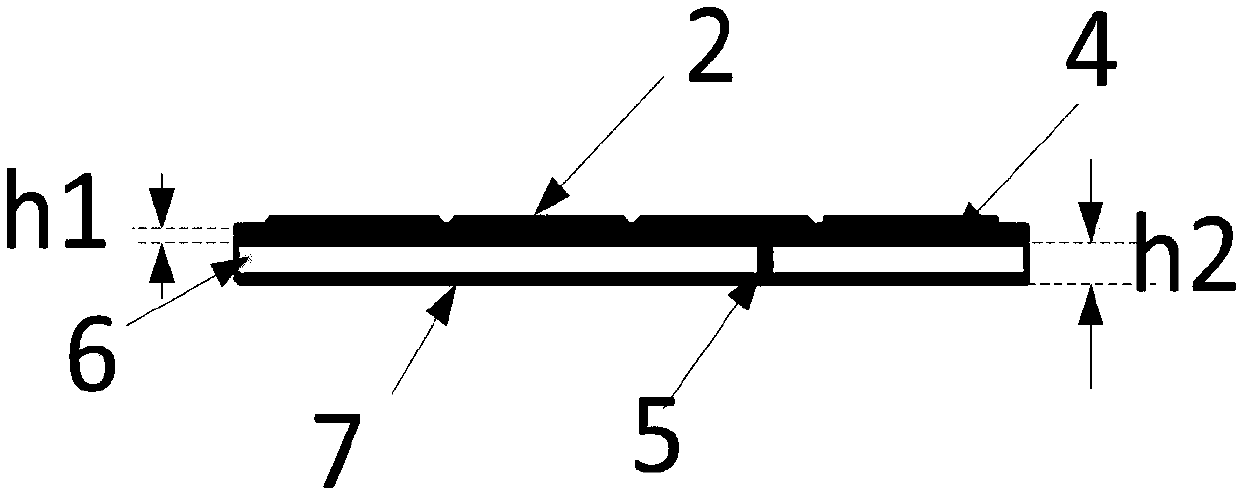
[0017] Such as figure 1 , 2 It is the antenna structure of the present invention, except for the feeding point, the whole antenna structure is symmetrical to the center. It includes an upper dielectric substrate (Rogers RT / duriod 5880) 4, a RIS surface arranged on the back of the upper dielectric substrate 4, a square radiation patch 1 printed on the upper surface of the upper dielectric substrate 4, and square radiation patches evenly arranged around it. 10 pieces of square parasitic patch 2 coplanar with piece 1. The coaxial inner conductor 5 passes through the surface of the RIS and is welded to the upper dielectric substrate 4 on the square radiation patch 1 . Specific dimensions: Lgnd=64mm, W=24mm, F=2mm, C1=14mm, G1=1mm, h1=1.575mm.

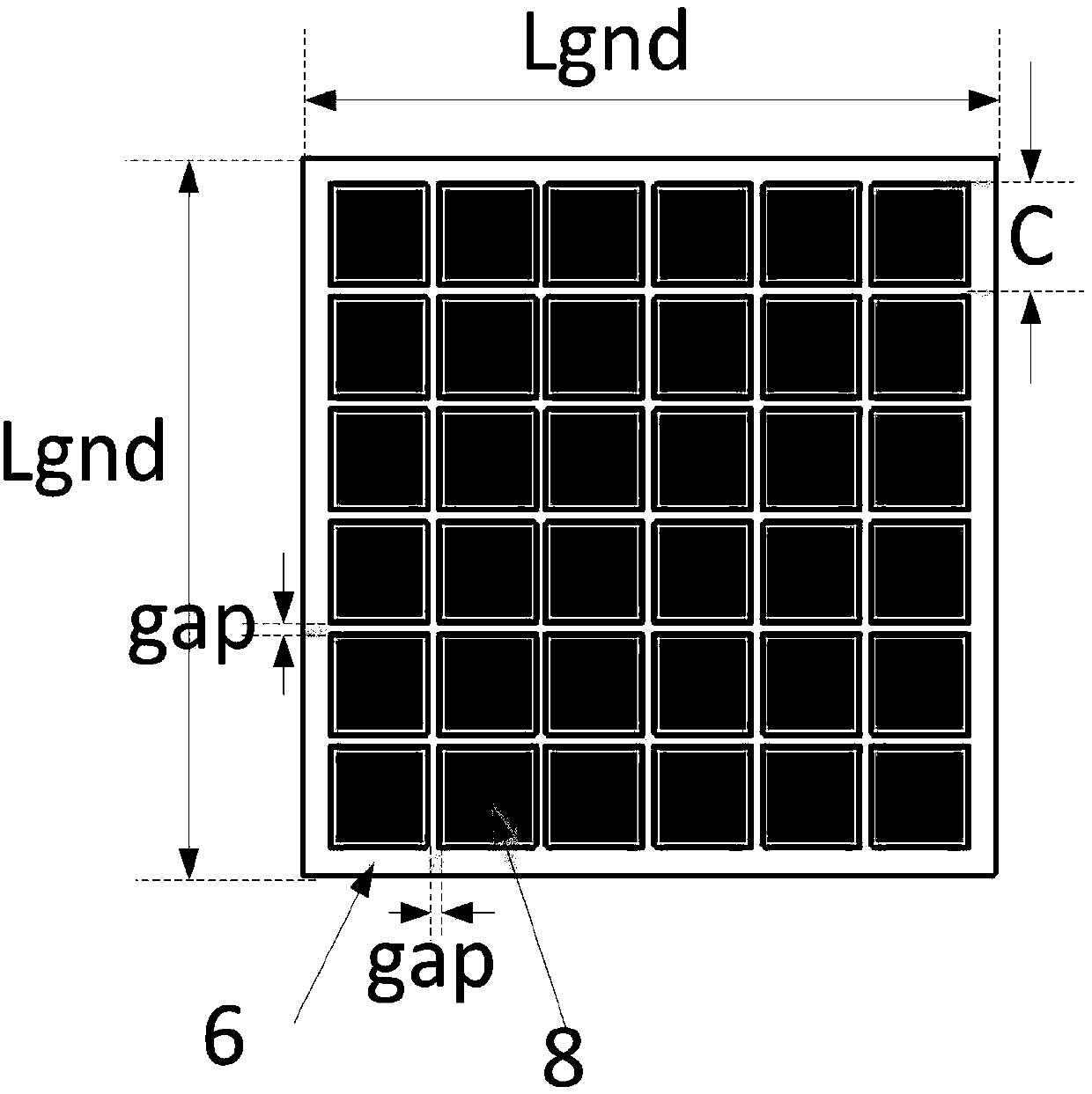
[0018] Such as image 3 , Figure 4 It is a RIS surfa...


PUM


Abstract

The invention discloses a broadband miniaturized patch antenna, which belongs to the field of wireless communication. The antenna comprises an upper layer medium substrate, a radiation patch disposedat the center of the front face of the upper layer medium substrate, a plurality of parasitic patches arranged at the periphery of the upper layer medium substrate, a resistor impedance surface (RIS)disposed at the back face of the upper layer medium substrate, and a coaxial cable. The invention is advantageous in that through the introducing of the resistor impedance surface (RIS) and the coplanar parasitic patches, good direction consistency and miniaturization can be provided under the prerequisite that bandwidth is wide.

Description

technical field [0001] The invention belongs to the field of wireless communication, in particular to a broadband miniaturized patch antenna loaded with a parasitic patch and an electrical impedance surface. Background technique [0002] Patch antennas are widely used due to their advantages of small size, light weight, low profile, and easy integration with circuits. For the patch antenna, it is usually considered to be installed on a certain platform, so a significant front-to-back radiation ratio is required to minimize the impact of the platform on the input impedance and radiation characteristics of the antenna. [0003] An antenna element design with a significant front-to-back radiation ratio can use a metal backing or a high-permittivity dielectric substrate. The dielectric resonator antenna belongs to the latter, which has a wider bandwidth and higher gain. However, the manufacturing cost of this antenna is not cheap, and it is not easy to integrate with the radio ...

Claims


Application Information

Patent Timeline
Patent Type & Authority Applications(China)
IPC IPC(8): H01Q9/04H01Q1/50
CPCH01Q1/50H01Q9/0407
Inventor 孟凡计王玉文刘影
Owner UNIV OF ELECTRONICS SCI & TECH OF CHINA
Why Eureka
Try Eureka