Neutron capturing treatment system

A treatment system, neutron technology, applied in treatment, X-ray/γ-ray/particle irradiation therapy, radiation therapy, etc., can solve the problems of bulky applicability, weak, unfavorable neutron therapy equipment installed in hospitals, etc., to achieve Easy deployment, effective treatment effect, and reduced transfer effect

Pending Publication Date: 2018-12-18
INST OF HIGH ENERGY PHYSICS CHINESE ACADEMY OF SCI
View PDF3 Cites 4 Cited by
  • Summary
  • Abstract
  • Description
  • Claims
  • Application Information

AI Technical Summary

Problems solved by technology

Obviously, the structure of the neutron therapy device itself is very large. To drive the rotation of the neutron therapy device through an external rotating device must be realized by a larger rotating device than the neutron therapy device. The rotation of the device and the rotating device also requires a very large space, and the whole device is not only heavy but also has poor applicability, which is not conducive to the miniaturization of the neutron therapy device, and is also not conducive to the installation of neutron therapy equipment in hospitals
Patents CN101829409B, CN206081353U and CN206167654U provide design schemes for neutron ray rotating irradiation devices, which improve the space, weight and volume of neutron treatment terminals to a certain extent, but their cost and miniaturization design It is still not as good as the solution with fixed irradiation angle

Method used


Image

  • Neutron capturing treatment system
  • Neutron capturing treatment system
  • Neutron capturing treatment system

Examples


Embodiment 1

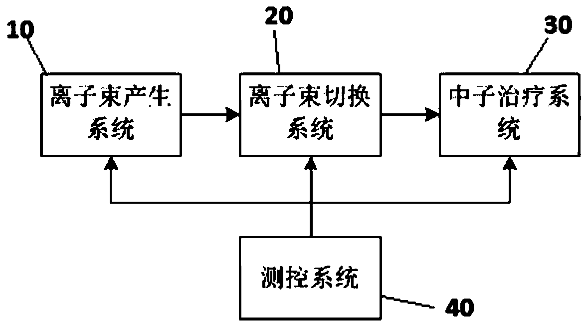
[0061] like Figure 1-Figure 4 As shown, a neutron capture therapy system includes: an ion beam generation system 10 , an ion beam switching system 20 , a neutron therapy system 30 , a treatment room 40 and a measurement and control system 50 .

[0062] The ion beam generating system 10 is used to provide a stable ion beam; the ion beam switching system 20 is connected to the ion beam generating system 10 for adjusting the direction of the ion beam, and the number of the ion beam switching systems 20 is at least two; The neutron therapy system 30 is connected with the ion beam switching system 20, and is used to irradiate the patient with neutrons. The number of the neutron therapy system 30 is at least two, and the neutron therapy system 30 corresponds to the ion beam switching system 20 one by one The measurement and control system 50 is connected with the ion beam generation system 10, the ion beam switching system 20 and the neutron therapy system 30, and is used to monito...

Embodiment 2

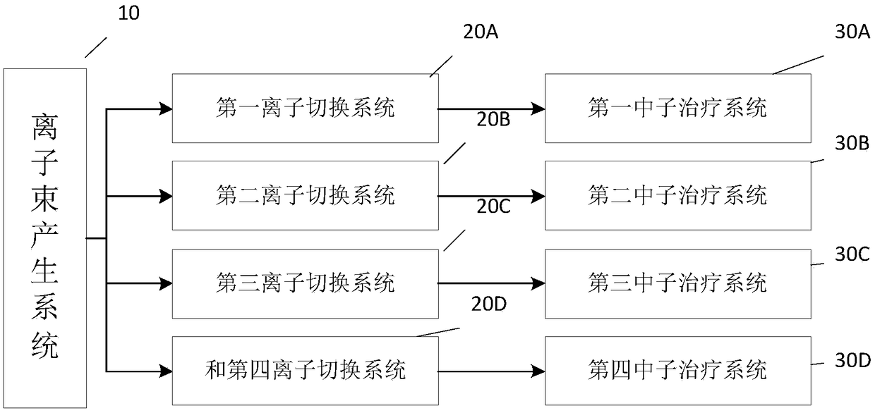
[0076] like Figure 2-Figure 4 As shown, this embodiment is an improved solution of Embodiment 1, and the difference from Embodiment 1 is that in this embodiment, the number of ion beam switching systems 20 is four, which are respectively the first ion switching system 20A and the second ion beam switching system 20A. Ion switching system 20B, the third ion switching system 20C and the fourth ion switching system 20D, the first ion switching system 20A is a horizontal ion switching system, the second ion switching system 20B is a vertical ion switching system, and the third ion switching system 20C is an inclined 45-degree ion switching system, and the fourth ion switching system 20D is an inclined 45-degree ion switching system;

[0077] The number of neutron therapy systems 30 is four, and the four neutron therapy systems are respectively the first neutron therapy system 30A, the second neutron therapy system 30B, the third neutron therapy system 30C and the fourth neutron t...

Embodiment 3

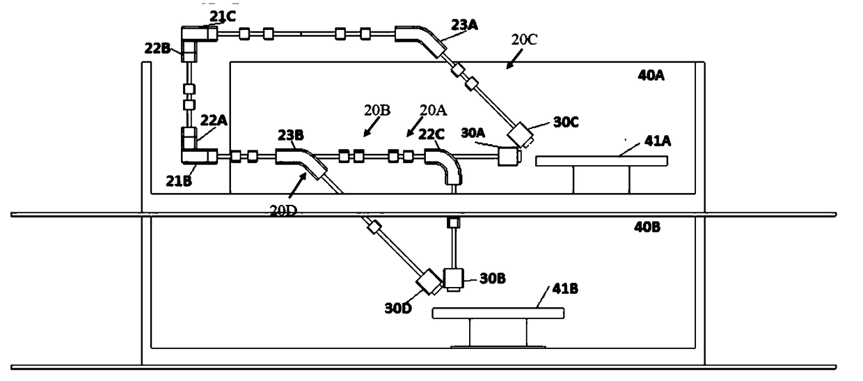
[0083] like Figure 3-Figure 4 As shown, the present embodiment is an improved solution of the second embodiment, and the difference from the second embodiment is that in the present embodiment, the direction of the ion beam is adjusted by placing deflection magnets alternately.

[0084] In this embodiment, the arrangement sequence of the deflection magnets of the first ion beam switching system 20A is: the first deflection magnet 21A in the horizontal direction 90 degrees - the second deflection magnet 21B in the horizontal direction 90 degrees, the ion beam is adjusted to the horizontal direction, and along the lead horizontally to the first neutron therapy system 30A;

[0085] The arrangement order of the deflection magnets of the second ion beam switching system 20B is: the first 90-degree deflection magnet 21A in the horizontal direction-the second 90-degree deflection magnet 21B in the horizontal direction-the third 90-degree deflection magnet 22C in the vertical directi...


PUM


Abstract

The invention belongs to the field of medical equipment, and discloses a neutron capturing treatment system. The neutron capturing treatment system comprises the components of an ion beam generating system which is used for supplying a stable ion beam; ion beam switching systems which are used for adjusting the direction of the iron beam to different directions, wherein at least two ion beam switching systems are arranged; neutron treatment systems which are used for irradiation treatment in different directions, wherein at least two neutron treatment systems are arranged and are in one-to-onecorrespondence with the ion beam switching systems; and treatment chambers, wherein each treatment chamber comprises at least two neutron treatment systems in different directions. According to the neutron capturing treatment system, the ion beam generating system utilizes a linear accelerator for performing ion acceleration; the ion beam switching system utilizes a deflecting magnet for performing ion beam direction adjustment; and the neutron treatment systems realize cooperation of the neutron treatment systems with different irradiation directions for use. Under a precondition that high treatment effect is ensured, miniaturization can be easily realized. The neutron capturing treatment system can be conveniently constructed in an existing hospital.

Description

technical field [0001] The invention belongs to the field of medical equipment, in particular to a neutron capture therapy system. Background technique [0002] The neutron source required by the Boron Neutron Capture Therapy (BNCT) device was previously provided by a reactor. Nuclear reactors themselves are expensive, and the use of nuclear reactors involves various regulations, which impose a heavy burden on doctors who perform treatment. Therefore, in order to be able to be installed in hospitals, the accelerator of the neutron therapy system needs to have the advantages of low cost and simple design, and according to the effect that boron-containing drugs can achieve in the current boron neutron capture therapy, the neutron source needs to be between 30 and A stable supply of neutron beams is maintained within 60 minutes. Therefore, medical devices that use accelerators as neutron sources for neutron capture therapy have higher stability requirements for accelerators. ...

Claims


Application Information

Patent Timeline
Patent Type & Authority Applications(China)
IPC IPC(8): A61N5/10
CPCA61N5/1077A61N2005/109
Inventor 张熹寅林洪涛陈朝斌
Owner INST OF HIGH ENERGY PHYSICS CHINESE ACADEMY OF SCI
Why Eureka
Try Eureka