
Gas supply system and gas supply method of ion source

A technology of gas supply system and ion source, applied in the direction of container discharge method, pipeline system, container filling method, etc., can solve the problems of ion beam instability, increase the operating frequency of operators, and unstable gas flow, etc., to ensure processing The effect of improving quality, ensuring uniformity, and stability

Active Publication Date: 2021-11-26
GUANGZHOU CANSEMI TECH INC
View PDF9 Cites 0 Cited by
  • Summary
  • Abstract
  • Description
  • Claims
  • Application Information

AI Technical Summary

Problems solved by technology

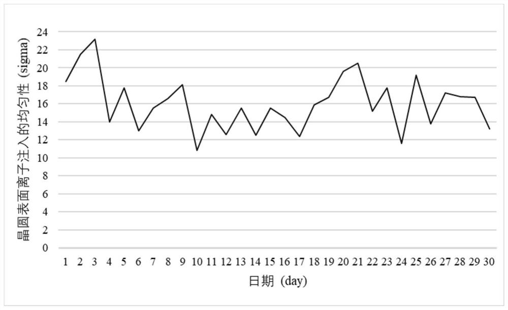
For the gas introduced in this way, since the heating temperature and pressure of the solid source placed in the ion source cannot be precisely controlled, and the remaining solid amount of the solid source gradually decreases as the gasification proceeds, the gas flow rate generated by the gasification of the solid source Very unstable, which causes the ion beam during ion implantation to be very unstable, which in turn affects the uniformity of implanted ions on the wafer surface
Furthermore, due to the limited loading capacity of the ion source, it can only accommodate a small number of solid sources. After a small amount of solid source is gasified, the ion source needs to be maintained, which greatly shortens the maintenance cycle of the ion source and increases the number of operators. operating frequency and reduce the lifetime of the ion source

Method used


Image

  • Gas supply system and gas supply method of ion source
  • Gas supply system and gas supply method of ion source
  • Gas supply system and gas supply method of ion source

Examples


Embodiment Construction

[0070] The present invention will be described in further detail below in conjunction with the accompanying drawings and specific embodiments. The advantages and features of the present invention will become clearer from the following description. It should be noted that all the drawings are in a very simplified form and use imprecise scales, and are only used to facilitate and clearly assist the purpose of illustrating the embodiments of the present invention.

[0071] As used in this specification, the singular forms "a", "an" and "the" include plural referents unless the content clearly dictates otherwise. As used in this specification, the term "or" is generally employed in its sense including "and / or" unless the content clearly dictates otherwise. As used in this specification, the terms "first", "second", etc. are used for descriptive purposes only, and cannot be interpreted as indicating or implying relative importance or implicitly specifying the quantity of indicated...


PUM


Abstract

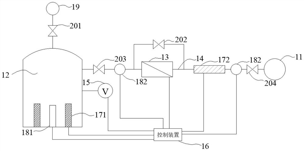
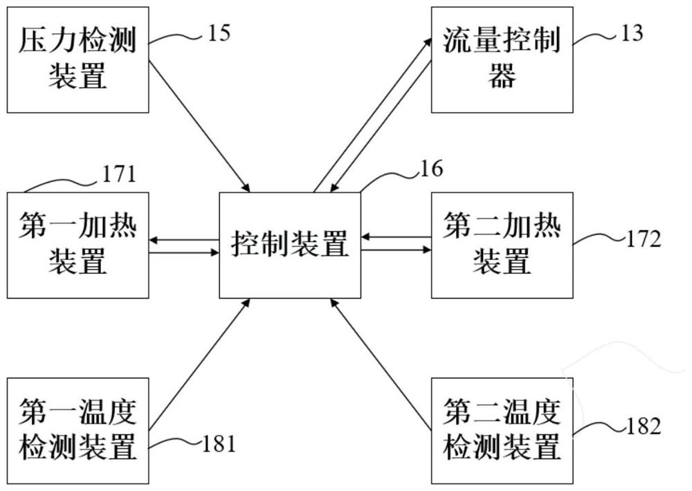
The invention provides a gas supply system and a gas supply method of an ion source. The gas supply system comprises a reaction cavity, a first heating device, a flow controller and a gas pipeline; the reaction cavity is used for placing a solid source; one end of the gas pipeline is connected with the reaction cavity, and the other end of the gas pipeline is connected with the ion source; and the first heating device is arranged on the reaction cavity and used for heating the solid source to a preset temperature so that the solid source can be gasified, and gas obtained after the solid source is gasified flows out of the reaction cavity and enters the ion source through the gas pipeline. The gas supply system can heat and gasify the solid source and provide stable gas flow for the ion source, so that the uniformity of ion implantation on the surface of a wafer is ensured, the productivity of ion implantation of the wafer is improved, and meanwhile, the maintenance period of the ion source is prolonged.

Description

technical field [0001] The invention relates to the technical field of semiconductor manufacturing, in particular to a gas supply system and a gas supply method for an ion source. Background technique [0002] Ion implanter is a key equipment in the manufacturing process of integrated circuits. Ion implantation is a technique for doping the area near the surface of the semiconductor wafer. The purpose is to change the carrier concentration and conductivity type of the semiconductor. During ion implantation, the gas source to be injected needs to be introduced into the electric field of the ion source, and be ionized into ions in the electric field of the ion source. If the substance to be injected is a solid source, it needs to be heated and vaporized to make it into a gas phase before being introduced into the ion source. [0003] Existing ion implanters generally adopt the method of loading a solid source into the ion source, and introducing gas in a manner of gasifying t...

Claims


Application Information

Patent Timeline
Patent Type & Authority Applications(China)
IPC IPC(8): F17C7/02F17C13/00F17C13/02F17C13/04F17D1/02F17D3/01
CPCF17C7/02F17C13/00F17C13/025F17C13/026F17C13/04F17D1/02F17D3/01F17C2201/0109F17C2201/0119F17C2205/0126F17C2205/0323F17C2223/0138F17C2225/0123F17C2227/0302F17C2227/0369F17C2227/045F17C2227/044F17C2227/046F17C2227/039F17C2250/0626F17C2250/0631F17C2260/02
Inventor 於鹏飞李飞逸汪东
Owner GUANGZHOU CANSEMI TECH INC
Learn More