Unit light guide plate, light guide plate unit, planar illuminating device and liquid crystal display device

A technology for lighting devices and light guide plates, which can be used in lighting devices, lighting and heating equipment, optical components, etc., and can solve problems such as weight reduction, large-scale processing limits, and weight reduction.

Inactive Publication Date: 2009-07-29
FUJIFILM CORP
View PDF2 Cites 24 Cited by
  • Summary
  • Abstract
  • Description
  • Claims
  • Application Information

AI Technical Summary

Problems solved by technology

[0020] However, the light guide plates described in Patent Documents 1 to 3 can provide a high-brightness and uniform lighting device. However, in order to increase the size, the thickness of the light guide plate itself must be increased so that the light reaches a position farther from the light source.
That is, in the illuminating device using the light guide plate disclosed in these documents, there is a problem that reduction in thickness and weight cannot be achieved.
[0021] In addition, since the shapes described in Patent Documents 1 to 3 include a shape that tends to decrease in thickness with distance from the incident position of the light source, or a flat plate shape, there is a limit to the reach distance of light. The increase in the overall size of the lighting device of the light guide plate disclosed in the literature also has a limit
[0022] Also, in the planar lighting device using the light guide plate described in Patent Document 4, in order to increase the overall size and make the light from the light source reach a farther position, the thickness of the light guide plate itself must be increased.
That is, even if the overall thickness of the planar lighting device is reduced, there is still a limit, and there is a problem that reduction in thickness and weight reduction beyond that level cannot be achieved.
[0023] In addition, in the flat plate described in Patent Document 4, or the light guide plate whose thickness decreases as it moves from the center to the periphery, there is a limit to the reach distance of light, so there is also a problem that there is a limit to the size-up process.
[0024] Furthermore, if such a light guide plate is used, the overall size is increased, and since the length of the light guide has a limit, there is also the problem that the in-plane uniformity of the brightness of the light exit surface of the light guide plate cannot be fully realized.

Method used


Image

  • Unit light guide plate, light guide plate unit, planar illuminating device and liquid crystal display device
  • Unit light guide plate, light guide plate unit, planar illuminating device and liquid crystal display device
  • Unit light guide plate, light guide plate unit, planar illuminating device and liquid crystal display device

Examples


Embodiment Construction

[0175] The unit light guide plate of the first aspect of the present invention, the light guide plate unit, and the planar illuminating device using them will be specifically described based on preferred embodiments shown in the drawings.

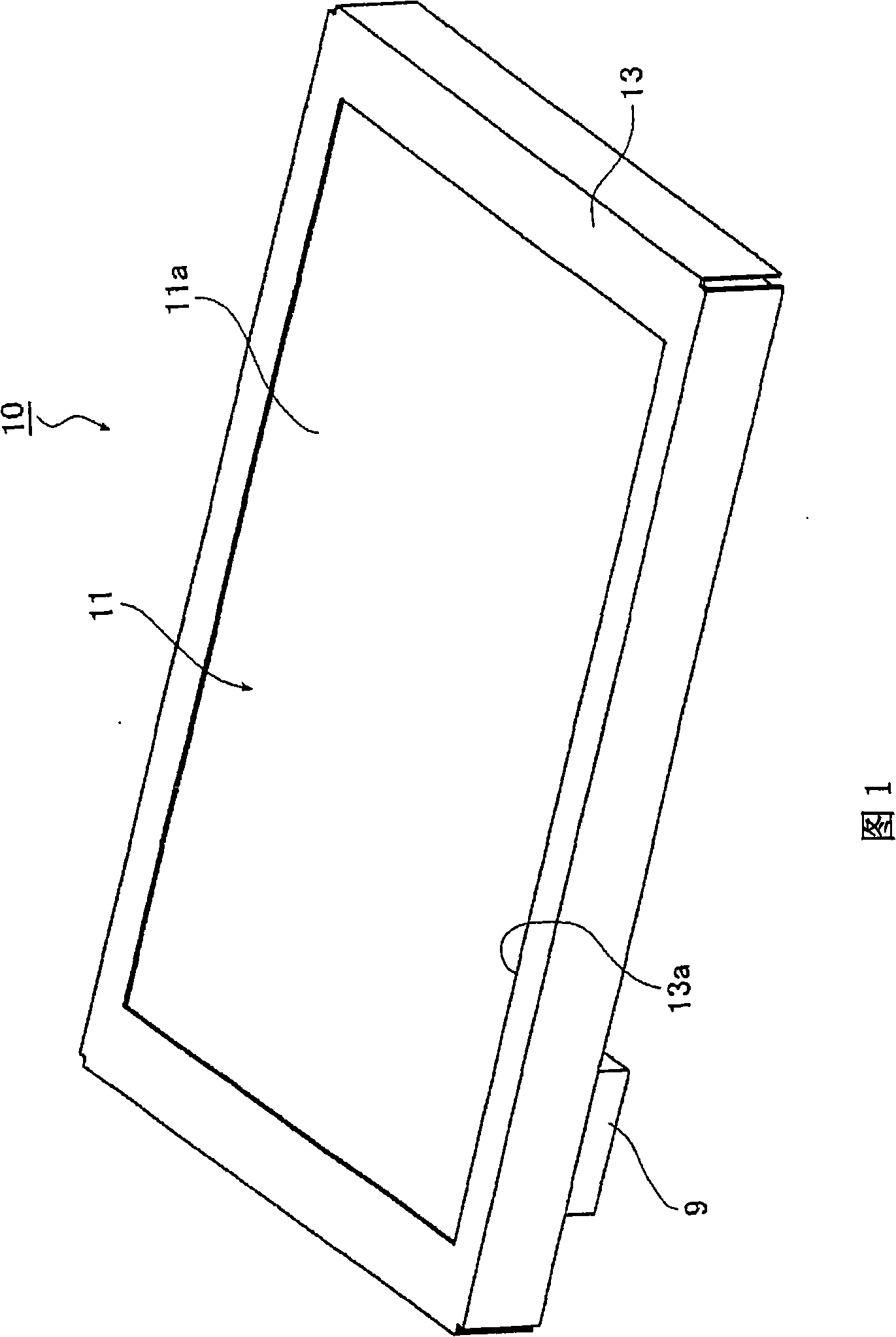
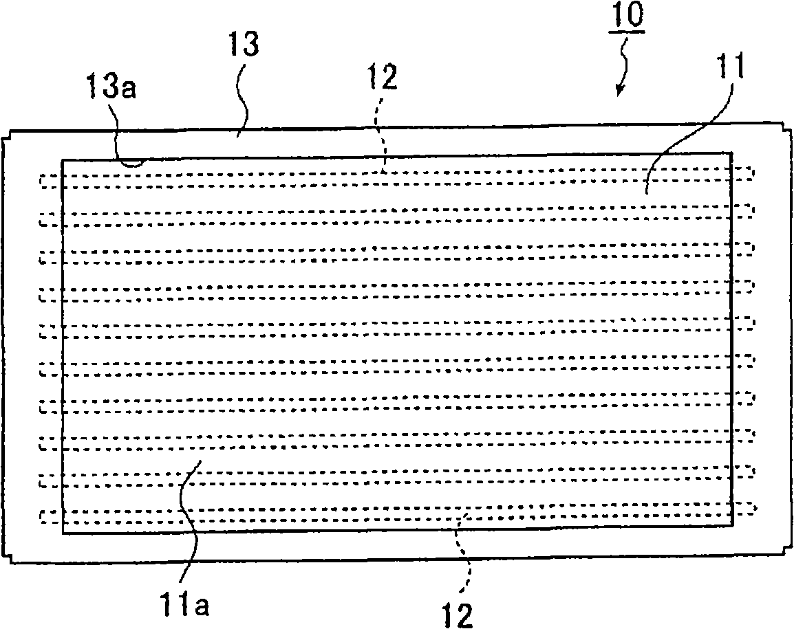
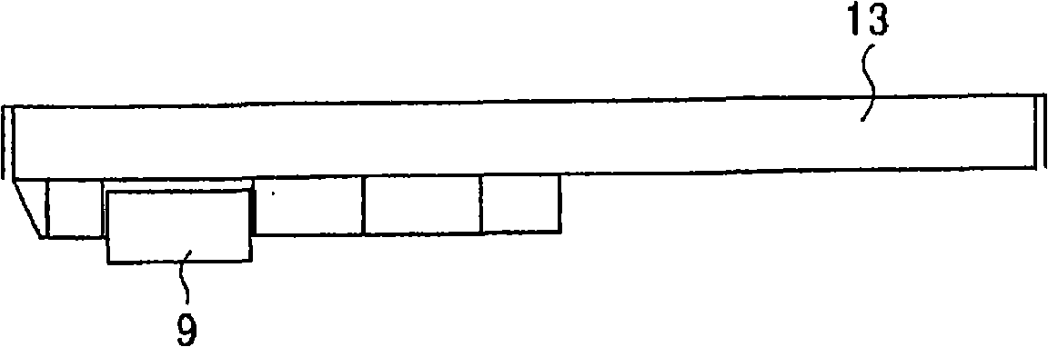
[0176] Fig. 1 is a schematic perspective view showing an appearance of an embodiment of a planar illuminating device according to a third embodiment of the first aspect of the present invention, viewed from a light exit surface side. Figure 2A , Figure 2B , Figure 2C with Figure 2D They are respectively a front view, a bottom view, a side view and a back view showing the planar lighting device shown in FIG. 1 . For ease of understanding, these drawings and the drawings described below are also included in an enlarged manner along the thickness direction of the planar lighting device.

[0177] Figure 1 and Figure 2A ~ Figure 2D As shown, the planar lighting device 10 includes a lighting device main body 11, which has a plurality of l...


PUM


Abstract

A unit light guide plate and a light guide plate unit are provided with a light outputting surface; a thick section substantially at the center of the light outputting surface; a thin end sections formed on the both sides of the thick section; a half section of a parallel groove formed on the rear side of the light outputting surface for storing a linear light source; an inclined rear section which becomes thinner toward the thin end section from the thick section; and a scattering means for scattering light which enters the thin end section from the light source stored in the parallel groove and propagates inside the inclined rear section.Alternatively, the unit light guide plate is provided with a spot light source; a light outputting surface for outputting light; a rear surface facing the light outputting surface; side surfaces connected to the light outputting surface and the rear surface; a light entering section, which is arranged substantially at the center of the rear surface, with a spot light source arranged, and permits incident light to enter; and a scattering means for outputting the entered light from a light outputting surface. A distance between the light outputting surface and the rear surface increases as it separates from the light entering section. A planar illuminating device and a liquid crystal display device are provided by using such unit light guide plate and the light guide plate unit.

Description

technical field [0001] The present invention relates to a unit light guide plate and a light guide plate assembly constituting a transparent light guide plate that diffuses light incident from a linear light source or a point light source arranged linearly in the surface direction, and emits more uniform illumination light from the light exit surface. And a planar lighting device using it, a unit light guide plate that converts incident light from a point light source into planar outgoing light, a planar lighting device and a liquid crystal display device using it. Background technique [0002] Conventionally, liquid crystal display devices employ a backlight unit that irradiates light from the rear side of a liquid crystal panel (LCD) to illuminate the liquid crystal panel. The backlight assembly is generally composed of the following components: a light source for illumination; a light guide plate that diffuses the light emitted from the light source to illuminate the liqu...

Claims


Application Information

Patent Timeline
Patent Type & Authority Applications(China)
IPC IPC(8): F21V8/00F21S2/00G02B6/00G02F1/13357F21Y101/02F21Y103/00
Inventor 仓光昌之远藤俊明
Owner FUJIFILM CORP
Why Eureka
Try Eureka