Fibular settlement nail

A technique of settlement nails and fibula, applied in the directions of internal bone synthesis, internal fixator, fixator, etc., can solve the problems of patients unable to obtain the expected recovery results and the failure of the augmentation operation, so as to eliminate or reduce the pain of the knee joint and relieve the knee joint. Pain and force-reducing effects

Inactive Publication Date: 2018-02-09
PAONAN BIOTECH
View PDF0 Cites 1 Cited by
  • Summary
  • Abstract
  • Description
  • Claims
  • Application Information

AI Technical Summary

Problems solved by technology

[0004] In the above treatment method, after the patient's fibula is amputated, there is no appropriate connecting member to limit and connect the two amputated fibula F1 and F2. Clinically, if Figure 18 As shown, the fibula F1, which is cut off at the upper end, will often turn outward, or in the recovery process after the cut-

Method used


Image

  • Fibular settlement nail
  • Fibular settlement nail
  • Fibular settlement nail

Examples


Embodiment Construction

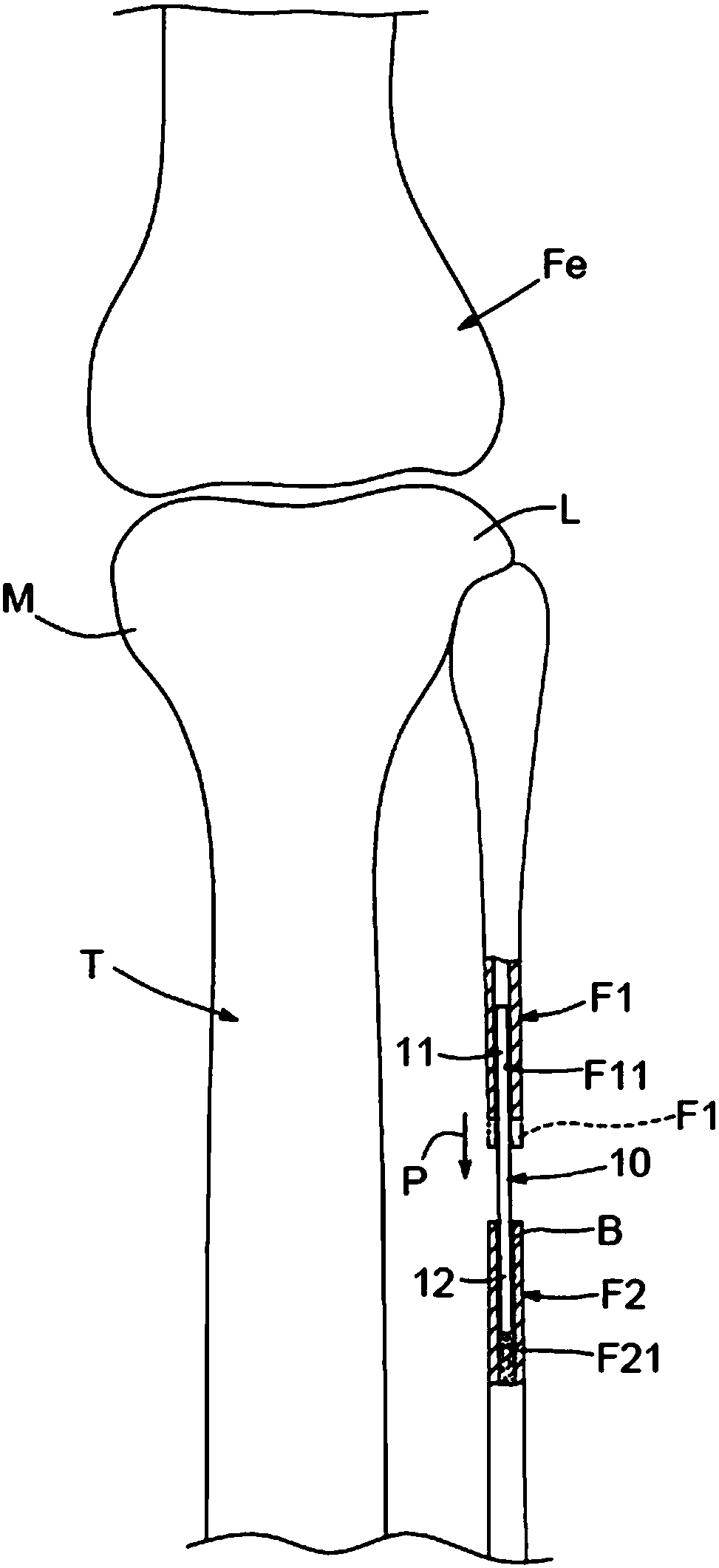
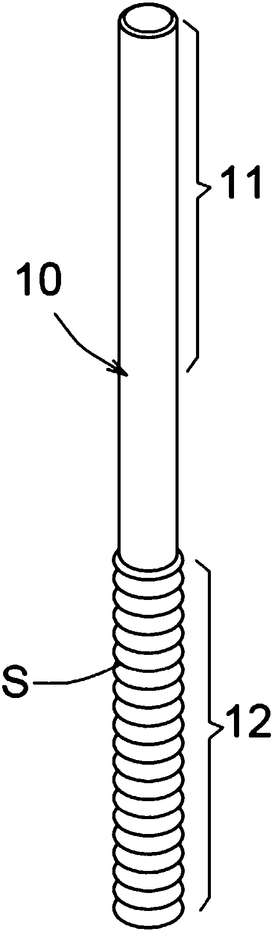
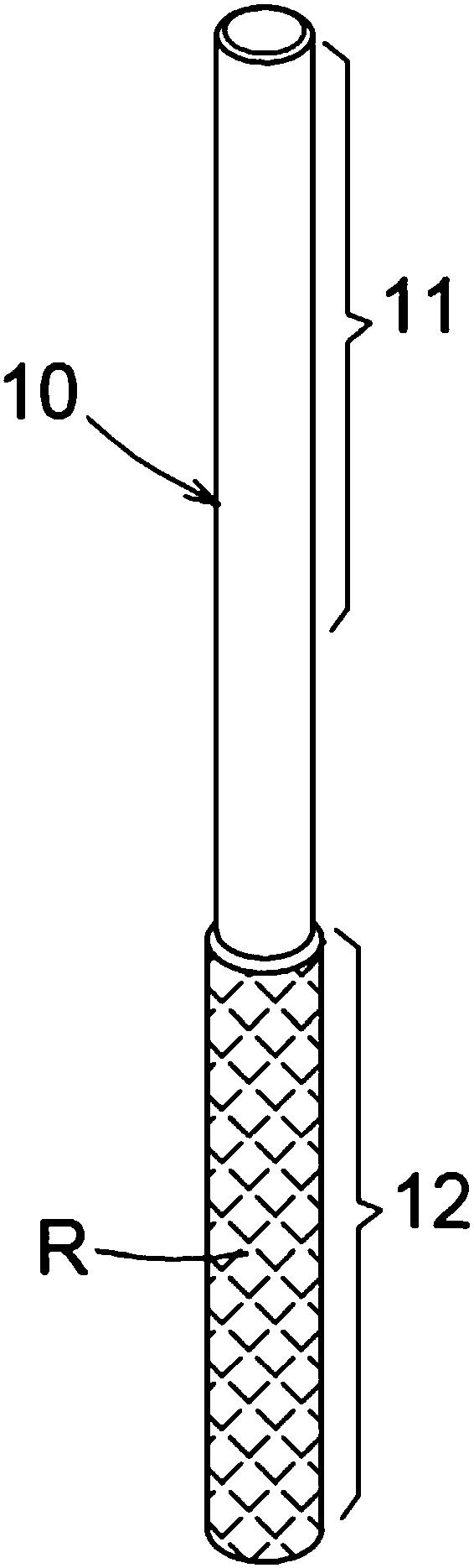
[0053] see Figure 1-17 As shown, the present invention relates to a fibula sinker nail, which includes a long and long nail body 10, and the two ends of the nail body 10 in the axial direction are defined as a first nail segment 11 and a second nail segment 12. The nail segment 11 is used to penetrate into the bone cavity F11 of one fibula F1 of the truncated fibula, and the second nail segment 12 is used to penetrate into the bone cavity F21 of the other fibula F2 of the truncated fibula, and the first At least one of the nail segment 11 or the second nail segment 12 can move relatively in the corresponding fibula bone cavity F11 or F21; thereby, the truncated fibula F1 or F2 can be as follows: figure 1 As shown in the P direction of , the relative movement along the nail body 10 occurs with the subsidence of the tibia T, and the nail body 10 is used to limit the lateral deviation of the two truncated fibula F1 and F2, so as to avoid the truncated fibula F1 and F2 Lateral ...


PUM


Abstract

A fibula sinking nail, comprising a longitudinally long nail body, the two ends of the nail body in the axial direction are defined as a first nail segment and a second nail segment, and the first nail segment is used to penetrate into the truncated fibula the bone cavity of one fibula, and the second nail segment is used to penetrate into the bone cavity of the other fibula of the truncated fibula, and at least one of the first nail segment or the second nail segment, It can move relatively in the bone cavity of the corresponding fibula, so that the truncated fibula can move relative to the tibial subsidence along the nail body, and use the nail body to restrict the two truncated fibula to produce lateral movement. offset.

Description

technical field [0001] The invention relates to a fibula sinking nail, especially a kind for penetrating into the truncated fibula, so that the truncated fibula can move along the fibula settling nail with tibial settlement, and the truncated fibula can be restricted by the nail body. The two fibula are displaced laterally. Background technique [0002] At present, for the treatment of knee joint lesions, most of them use the method of replacing the artificial joint to relieve the patient's lesion. However, due to the replacement of the artificial joint, most of the patient's bones must be removed, and the patient must cut a large wound, making this type of operation It has the disadvantages of greater risk and slower recovery. [0003] Aiming at the medial knee joint lesions caused by osteoporosis, Professor Zhang Yingze from China proposed the theory of "uneven knee joint subsidence". The outer side of the tibial bone is supported by the fibula, so the tibial plateau wil...

Claims


Application Information

Patent Timeline
IPC IPC(8): A61B17/72
CPCA61B17/7216
Inventor 叶中权
Owner PAONAN BIOTECH
Why Eureka
Try Eureka