Filter dust removal device
A filter dust removal device and filter technology, which is applied in the direction of dispersed particle filtration, transportation and packaging, and separation of dispersed particles. It can solve the problems of self-cleaning and failure of filter devices, etc., so as to increase the contact area and realize reciprocating motion. , enhance the filtering effect
- Summary
- Abstract
- Description
- Claims
- Application Information
AI Technical Summary
Problems solved by technology
Method used
Image

Examples
specific Embodiment approach 1
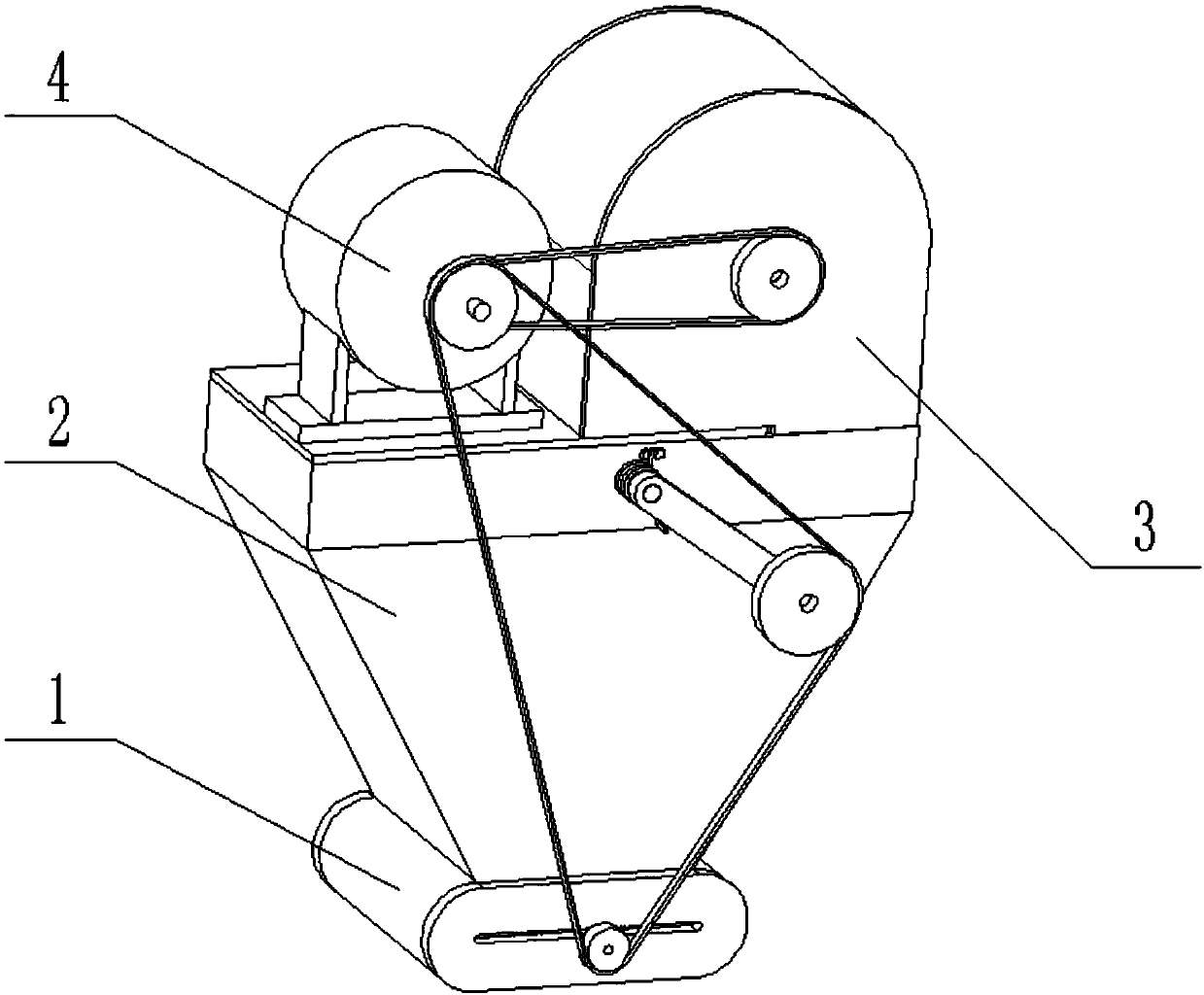
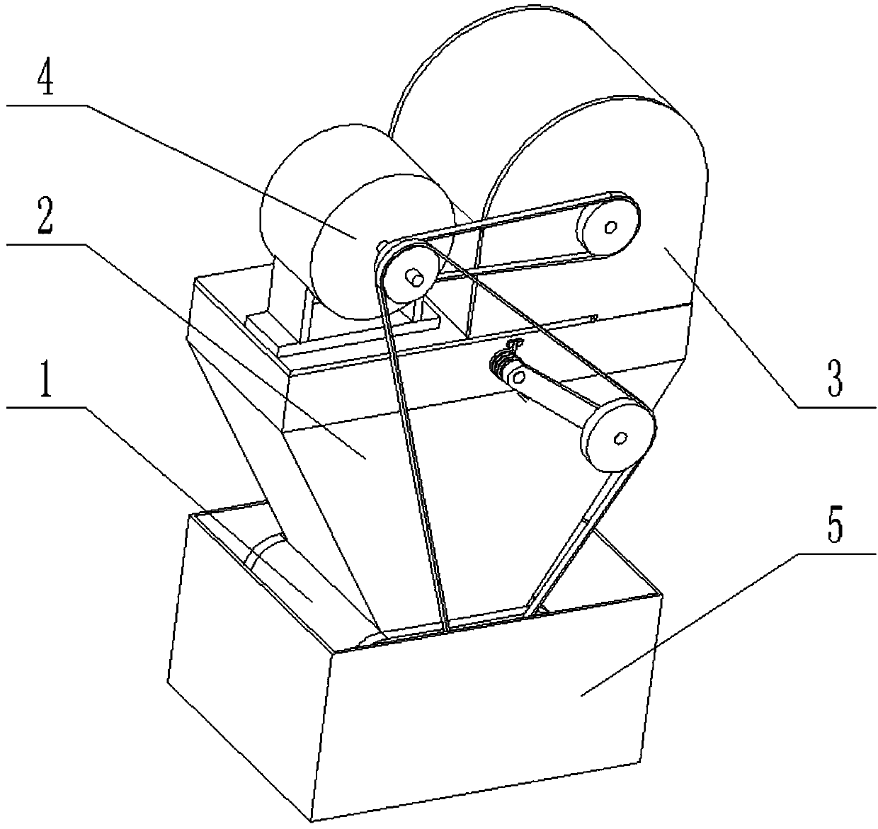
[0040] Combine below Figure 1-14 Describe this embodiment, a filter and dust removal device, including a filter 1, a ventilation box 2, a blower device 3 and a driving device 4, the filter 1 is fixedly connected and communicated with the lower end of the ventilation box 2, and the ventilation box 2 The upper end is fixedly connected and communicated with the blower device 3, the drive device 4 is connected to the upper end of the ventilation box 2 by bolts, and the blower device 3 and the drive device 4 are connected by a belt;
[0041]Described ventilation box 2 is provided with fork 2-4, torsion spring 2-5 and tensioning pulley 2-6, and one end of described fork 2-4 is connected on the ventilation box 2 in rotation, and the fork 2-4 The other end is rotatably connected with a tensioning wheel 2-6, and a torsion spring 2-5 is arranged between the swing rod 2-4 and the ventilation box 2;
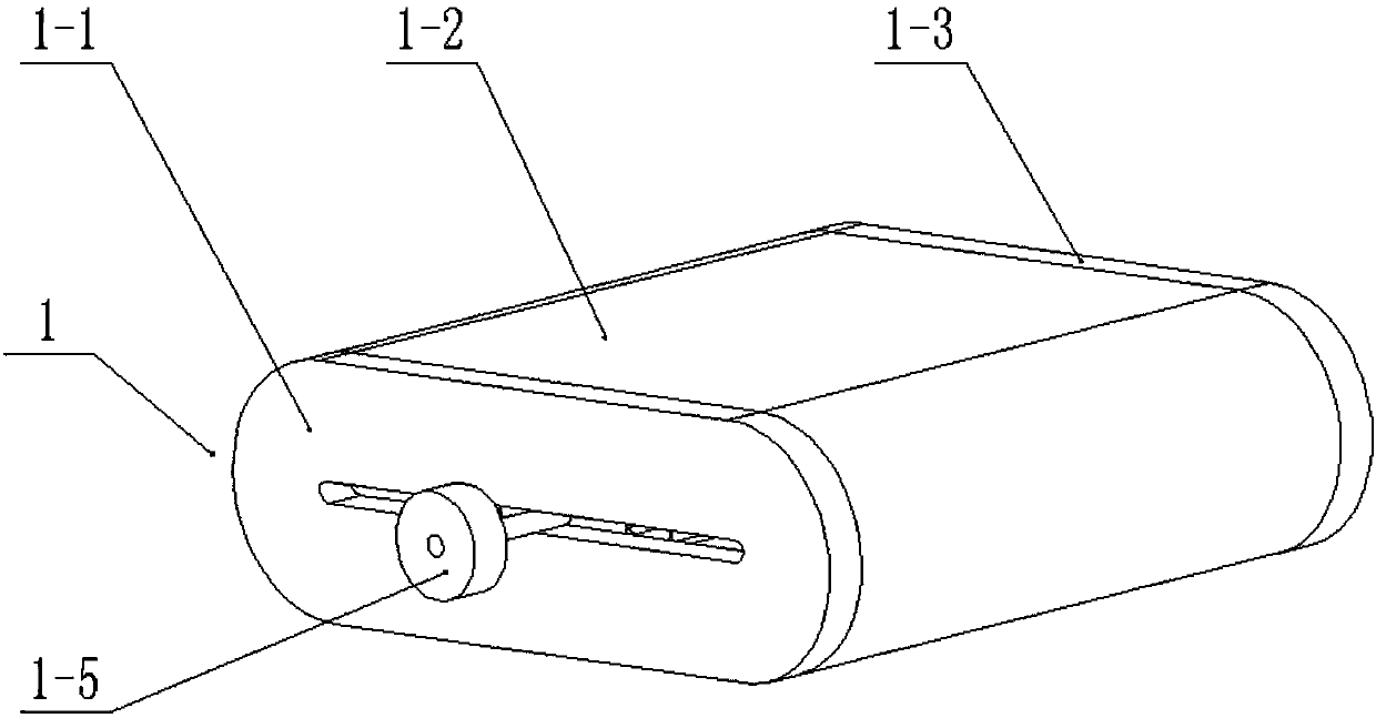
[0042] The filter 1 comprises a front end cover 1-1, a filter plate 1-2, a rear end co...
specific Embodiment approach 2
[0043] Combine below Figure 1-14 Describe this embodiment, this embodiment will further explain the first embodiment, the ventilation box 2 includes a ventilation box body 2-1, an air inlet 2-2 and an air outlet 2-3, and the inside of the ventilation box body 2-1 is hollowed out , the air inlet 2-2 is arranged at the right end of the upper end surface of the ventilation box body 2-1, the air outlet 2-3 is arranged at the lower end of the ventilation box body 2-1, and the air inlet 2-2 is used to connect and It communicates with the blower device 3, and the air outlet 2-3 is used to connect and communicate with the filter 1, and introduce air into the filter 1 for filtering treatment.
specific Embodiment approach 3
[0044] Combine below Figure 1-14 Describe this embodiment mode, this embodiment mode will be further described to embodiment one, and described filter plate 1-2 inside forms the filter cavity of hollow out, and the upper and lower ends of filter plate 1-2 inner wall are all provided with sawtooth structure; During work, because The upper and lower ends of the inner wall of the filter plate 1-2 are provided with a sawtooth structure, which can effectively increase the contact area between the filter material and the air, and is beneficial to enhance the filtering effect. At the same time, a hollow filter cavity is formed inside the filter plate 1-2, which can Set the filter material at the upper end of the filter cavity as a filter material with a larger filter pore size, such as a metal filter mesh or fiber filter paper with a filter hole greater than 500mm; set the filter material at the lower end of the filter cavity with a filter material with a smaller filter pore size, su...
PUM
| Property | Measurement | Unit |
|---|---|---|
| angle | aaaaa | aaaaa |
Abstract
Description
Claims
Application Information
 - R&D
- Intellectual Property
- Life Sciences
- Materials
- Tech Scout
- Unparalleled Data Quality
- Higher Quality Content
- 60% Fewer Hallucinations
Browse by: Latest US Patents, China's latest patents, Technical Efficacy Thesaurus, Application Domain, Technology Topic, Popular Technical Reports.
© 2025 PatSnap. All rights reserved.Legal|Privacy policy|Modern Slavery Act Transparency Statement|Sitemap|About US| Contact US: help@patsnap.com